How to determine the heat flux. The heat flow is
HEAT FLOW
HEAT FLOW
The amount of heat transferred through isothermal. in units time. The dimension of T. p. coincides with the dimension of power. T. p. is measured in watts or kcal / h (1 kcal / h \u003d 1.163 W). T. p., referred to units. isothermal surfaces, called density T. p., beats. Etc. or heat load; usually denoted q, measured in W / m2 or kcal / (m2 h). Density T. p. is a vector, any component of which is numerically equal to the amount of heat transferred in units. time in units area perpendicular to the direction taken.
Physical Encyclopedic Dictionary. - M.: Soviet Encyclopedia. . 1983 .
HEAT FLOW
A vector directed in the direction opposite to the temperature gradient and equal in abs. the amount of heat passing through isothermal. surface per unit of time. It is measured in watts or kcal / h (1 kcal / h \u003d 1.163 W). T. p., related to the unit isothermal. surfaces, called density T. p. or beats. T. p., in technology - heat load. Units beats. T. p. serve as W / m 2 and kcal / (m 2 h).
Physical encyclopedia. In 5 volumes. - M.: Soviet Encyclopedia. Editor-in-Chief A. M. Prokhorov. 1988 .
See what "HEAT FLOW" is in other dictionaries:
heat flow- Heat flux - the amount of heat passing through the sample per unit time. [GOST 7076 99] Heat flow - the flow of heat energy transferred in the heat exchange process. [Terminological dictionary for concrete and reinforced concrete. FSUE… … Encyclopedia of terms, definitions and explanations of building materials
The amount of heat passing per unit time through an arbitrary isothermal surface ... Big Encyclopedic Dictionary
- (a. heat flow, heat flux, rate of heat flow; n. Warmefluβ, Warmestromung; f. courant calorifique, flux de chaleur; i. corriente termico, torrente calorico, flujo termico) amount of heat transferred through isothermal. surface per unit ... ... Geological Encyclopedia
The amount of heat transferred through any surface in the process of heat transfer. It is characterized by the density of T. p., which is the ratio of the amount of heat transferred through the surface to the time interval for which this ... ... Encyclopedia of technology
heat flow- — [Ya.N. Luginsky, M.S. Fezi Zhilinskaya, Yu.S. Kabirov. English Russian Dictionary of Electrical Engineering and Power Engineering, Moscow, 1999] Topics in electrical engineering, basic concepts EN thermal currentthermal flowheat fluxthermal flux ... Technical Translator's Handbook
Heat flux Q- W is the amount of heat passing through the building envelope per unit time.
1. Homogeneous wall. Consider a homogeneous wall thickness (Fig. 1-7), the thermal conductivity, which is constant. Constant temperatures are maintained on the outer surfaces of the wall. The temperature changes only in the direction of the x-axis. In this case, the temperature field is one-dimensional, the isothermal surfaces are flat and are located perpendicular to the x axis.
At a distance x, we select a layer of thickness inside the wall bounded by two isothermal surfaces. Based on Fourier's law [equation (1-1)] for this case, we can write:
![]()
Density heat flow q under stationary thermal conditions is constant in each section, therefore
![]()
The integration constant C is determined from the boundary conditions, namely, for a at . Substituting these values into equation (b), we have:
![]()
From equation (c), the unknown value of the heat flux density q is determined, namely:
![]()
Consequently, the amount of heat transferred through a unit of the wall surface per unit of time is directly proportional to the thermal conductivity coefficient and the temperature difference of the outer surfaces and inversely proportional to the wall thickness.
Equation (1-2) is the calculation formula for the thermal conductivity of a flat wall. It connects four quantities: and . Knowing any three of them, you can find the fourth:
![]()
The ratio is called the thermal conductivity of the wall, and the reciprocal is called the thermal resistance. The latter determines the temperature drop in the wall per unit heat flux density.
If we substitute the found values of C and heat flux density q into equation (b), then we obtain the equation of the temperature curve
![]()
The latter shows that at a constant value of the thermal conductivity coefficient, the temperature of a homogeneous wall changes according to a linear law. In reality, due to its dependence on temperature, the thermal conductivity coefficient is a variable. If this circumstance is taken into account, then we obtain other, more complex calculation formulas.
For the vast majority of materials, the dependence of the thermal conductivity coefficient on temperature has a linear character of the form. In this case, based on the Fourier law for a flat wall, we have:
Dividing the variables and integrating, we get:
![]()
Substituting into equation (e) the boundary values of the variables, we have at
Subtracting equation (g) from equation (h), we obtain:
![]()
![]()

Rice. 1-7. Homogeneous flat wall.
The new calculation formula (1-4) is somewhat more complicated than formula (1-2). There we took the thermal conductivity constant and equal to some average value .
Equating each other the right parts of these formulas, we have:
![]()
Therefore, if it is determined by the arithmetic mean of the boundary values of the wall temperatures, then formulas (1-2) and (1-4) are equivalent.
Taking into account the dependence of the thermal conductivity coefficient on temperature, the equation for the temperature curve in the wall is obtained by solving equation (e) with respect to t and substituting the value C from (g), namely:

Therefore, in this case, the wall temperature does not change linearly, but along a curve. Moreover, if the coefficient b is positive, the convexity of the curve is directed upwards, and if it is negative - downwards (see Fig. 1-10).
2. Multilayer wall.
Walls consisting of several heterogeneous layers are called multilayer.
These are, for example, the walls of residential buildings, in which on the main brick layer there is an internal plaster on one side, and an external cladding on the other. The lining of furnaces, boilers and other thermal devices also usually consists of several layers.

Rice. 1-8. Multilayer flat wall.
Let the wall consist of three heterogeneous, but closely adjacent layers (Fig. 1-8). The thickness of the first layer of the second and third. Accordingly, the coefficients of thermal conductivity of the layers. In addition, the temperatures of the outer surfaces of the wall are known. The thermal contact between the surfaces is assumed to be ideal; we denote the temperature at the points of contact by .
In the stationary regime, the heat flux density is constant and the same for all layers. Therefore, based on equation (1-2), we can write:

From these equations, it is easy to determine the temperature differences in each layer:

The sum of the temperature differences in each layer is the total temperature difference. Adding the left and right parts of the system of equations (m), we obtain:
![]()
From the relation (n) we determine the value of the heat flux density:

By analogy with the above, you can immediately write the calculation formula for the -layer wall:

Since each term of the denominator in the formula (1-6) represents the thermal resistance of the layer, it follows from equation (1-7) that the total thermal resistance of the multilayer wall is equal to the sum of the partial thermal resistances.
Rice. 1-9. Graphical method for determining intermediate temperatures.
If the value of the heat flux density from equation (1-6) is substituted into equation (m), then we obtain the values of unknown temperatures:
Inside each layer, the temperature changes in a straight line, but for a multilayer wall as a whole, it is a broken line (Fig. 1-8). The values of unknown temperatures of a multilayer wall can also be determined graphically (Fig. 1-9). When plotting along the x-axis on any scale, but in the order of the layers, the values of their thermal resistances are plotted, and perpendiculars are restored. On the extreme of them, also on an arbitrary, but the same scale, the values \u200b\u200bof outside temperatures are plotted.
The resulting points A and C are connected by a straight line. The points of intersection of this line with the average perpendiculars give the values of the desired temperatures. With such a build. Hence,
![]()
Substituting the values of the segments, we get:

In a similar way, we prove that
![]()
Sometimes, for the sake of reducing calculations, a multilayer wall is calculated as a single-layer (uniform) thickness. In this case, the so-called equivalent thermal conductivity is introduced into the calculation, which is determined from the relation

Hence we have:

Thus, the equivalent thermal conductivity depends only on the values of thermal resistances and the thickness of the individual layers.
When deriving the calculation formula for a multilayer wall, we assumed that the layers closely adjoin each other and, due to ideal thermal contact, the contacting surfaces of different layers have the same temperature. However, if the surfaces are rough, close contact is impossible and air gaps form between the layers. Since the thermal conductivity of air is small, the presence of even very thin gaps can greatly affect the reduction of the equivalent thermal conductivity of a multilayer wall. A similar effect is exerted by the metal oxide layer. Therefore, when calculating and especially when measuring the thermal conductivity of a multilayer wall, attention should be paid to the density of contact between the layers.
Example 1-1. Determine the heat loss through a brick wall 5 m long, 3 m high and 250 mm thick if temperatures are maintained on the wall surfaces. Thermal conductivity coefficient of brick A = 0.6 W / (m ° C).
According to equation (1-2)
Example 1-2. Determine the value of the coefficient of thermal conductivity of the wall material if, with a thickness of mm and a temperature difference, the heat flux density is .
I. Measurement of the density of heat fluxes passing through the building envelope. GOST 25380-82.
Heat flux - the amount of heat transferred through an isothermal surface per unit time. Heat flow is measured in watts or kcal / h (1 W \u003d 0.86 kcal / h). The heat flux per unit of isothermal surface is called the heat flux density or heat load; usually denoted by q, measured in W / m2 or kcal / (m2 × h). The heat flux density is a vector, any component of which is numerically equal to the amount of heat transferred per unit time through a unit area perpendicular to the direction of the taken component.
Measurements of the density of heat fluxes passing through the building envelope are carried out in accordance with GOST 25380-82 "Buildings and structures. Method for measuring the density of heat fluxes passing through the building envelope".
This standard establishes a unified method for determining the density of heat fluxes passing through single-layer and multi-layer building envelopes of residential, public, industrial and agricultural buildings and structures during an experimental study and under their operating conditions.
The heat flux density is measured on the scale of a specialized device, which includes a heat flux converter, or is calculated from the results of emf measurement. on pre-calibrated heat flux transducers.
The scheme for measuring the heat flux density is shown in the drawing.
1 - enclosing structure; 2 - heat flow converter; 3 - emf meter;
tv, tn - temperature of internal and external air;
τн, τв, τ"в — the temperature of the outer, inner surfaces of the enclosing structure near and under the converter, respectively;
R1, R2 - thermal resistance of the building envelope and heat flux converter;
q1, q2 are the heat flux density before and after fixing the transducer
II. Infrared radiation. Sources. Protection.
Protection against infrared radiation in the workplace.
The source of infrared radiation (IR) is any heated body, the temperature of which determines the intensity and spectrum of the emitted electromagnetic energy. The wavelength with the maximum energy of thermal radiation is determined by the formula:
λmax = 2.9-103 / T [µm] (1)
where T is the absolute temperature of the radiating body, K.
Infrared radiation is divided into three areas:
shortwave (X = 0.7 - 1.4 microns);
medium wave (k \u003d 1.4 - 3.0 microns):
long-wavelength (k = 3.0 μm - 1.0 mm).
Electric waves of the infrared range mainly have a thermal effect on the human body. In this case, it is necessary to take into account: the intensity and wavelength with maximum energy; radiated surface area; duration of exposure per working day and duration of continuous exposure; intensity of physical labor and air mobility in the workplace; quality of overalls; individual characteristics of the worker.
Rays of the short-wave range with a wavelength of λ ≤ 1.4 μm have the ability to penetrate into the tissue of the human body by several centimeters. Such IR radiation easily penetrates through the skin and cranium into the brain tissue and can affect brain cells, causing severe damage to it, the symptoms of which are vomiting, dizziness, dilation of blood vessels in the skin, a drop in blood pressure, impaired circulation and respiration, convulsions, and sometimes loss of consciousness. When irradiated with short-wave infrared rays, an increase in the temperature of the lungs, kidneys, muscles and other organs is also observed. In the blood, lymph, cerebrospinal fluid, specific biologically active substances appear, there is a violation metabolic processes, the functional state of the central nervous system changes.
The rays of the medium wave range with a wavelength of λ = 1.4 - 3.0 microns are retained in the surface layers of the skin at a depth of 0.1 - 0.2 mm. Therefore, their physiological effect on the body is manifested mainly in an increase in skin temperature and heating of the body.
The most intense heating of the human skin surface occurs with IR radiation with λ > 3 µm. Under its influence, the activity of the cardiovascular and respiratory systems, as well as the thermal balance of the body, is disrupted, which can lead to heat stroke.
The intensity of thermal radiation is regulated based on the subjective sensation of the radiation energy by a person. According to GOST 12.1.005-88, the intensity of thermal exposure of workers from heated surfaces of process equipment and lighting fixtures should not exceed: 35 W/m2 with exposure to more than 50% of the body surface; 70 W/m2 when exposed to 25 to 50% of the body surface; 100 W/m2 when irradiating no more than 25% of the body surface. From open sources (heated metal and glass, open flame), the intensity of thermal radiation should not exceed 140 W / m2 with exposure of no more than 25% of the body surface and the mandatory use of personal protective equipment, including face and eye protection.
The standards also limit the temperature of the heated surfaces of the equipment in the working area, which should not exceed 45 °C.
The surface temperature of the equipment, inside which the temperature is close to 100 0C, should not exceed 35 0C.
q = 0.78 x S x (T4 x 10-8 - 110) / r2 [W/m2] (2)
The main types of protection against infrared radiation include:
1. time protection;
2. distance protection;
3. shielding, thermal insulation or cooling of hot surfaces;
4. increase in heat transfer of the human body;
5. personal protective equipment;
6. elimination of heat source.
Time protection provides for limiting the time spent by the radiation operating in the area of radiation. The safe time of a person's stay in the zone of action of IR radiation depends on its intensity (flux density) and is determined according to Table 1.
Table 1
Time of safe stay of people in the IR radiation zone
The safe distance is determined by formula (2) depending on the duration of stay in the working area and the allowable density of IR radiation.
The power of IR radiation can be reduced by design and technological solutions (replacement of the mode and method of heating products, etc.), as well as by coating the heating surfaces with heat-insulating materials.
There are three types of screens:
opaque;
· transparent;
translucent.
In opaque screens, energy electromagnetic oscillations, interacting with the substance of the screen, turns into thermal. In this case, the screen heats up and, like any heated body, becomes a source of thermal radiation. The radiation of the screen surface opposite to the source is conditionally considered as the transmitted radiation of the source. Opaque screens include: metal, alfa (from aluminum foil), porous (foam concrete, foam glass, expanded clay, pumice), asbestos and others.
In transparent screens, radiation propagates inside them according to the laws of geometric optics, which ensures visibility through the screen. These screens are made of various types of glass, film water curtains (free and flowing down the glass) are also used.
Translucent screens combine the properties of transparent and non-transparent screens. These include metal meshes, chain curtains, glass screens reinforced with metal mesh.
· heat-reflecting;
· heat-absorbing;
heat dissipative.
This division is rather arbitrary, since each screen has the ability to reflect, absorb and remove heat. The assignment of the screen to one or another group is determined by which of its abilities is more pronounced.
Heat-reflecting screens have a low degree of surface blackness, as a result of which they reflect a significant part of the radiant energy incident on them in the opposite direction. Alfol, sheet aluminum, galvanized steel are used as heat-reflecting materials.
Heat-absorbing screens are called screens made of materials with high thermal resistance (low thermal conductivity). Refractory and heat-insulating bricks, asbestos, and slag wool are used as heat-absorbing materials.
As heat-removing screens, water curtains are most widely used, freely falling in the form of a film, or irrigating another screening surface (for example, metal), or enclosed in a special casing made of glass or metal.
E \u003d (q - q3) / q (3)
E \u003d (t - t3) / t (4)
q3 is the flux density of IR radiation with the use of protection, W/m2;
t is the temperature of IR radiation without the use of protection, °C;
t3 is the temperature of IR radiation with the use of protection, °С.
The air flow directed directly at the worker allows to increase the removal of heat from his body in environment. The choice of air flow rate depends on the severity of the work performed and the intensity of the infrared radiation, but it should not exceed 5 m / s, since in this case the worker experiences unpleasant sensations (for example, tinnitus). The effectiveness of air showers increases when the air sent to the workplace is cooled or when finely sprayed water is mixed into it (water-air shower).
As personal protective equipment, overalls made of cotton and woolen fabrics, fabrics with a metal coating (reflecting up to 90% of IR radiation) are used. Goggles, shields with special glasses are designed to protect the eyes - light filters of yellow-green or blue color.
Therapeutic and preventive measures provide for the organization of a rational regime of work and rest. The duration of breaks in work and their frequency are determined by the intensity of IR radiation and the severity of the work. Along with periodic inspections, medical examinations are carried out to prevent occupational diseases.
III. Instruments used.
To measure the density of heat fluxes passing through the building envelope and to check the properties of heat shields, our specialists developed devices of the series.

Application area:
Devices of the IPP-2 series are widely used in construction, scientific organizations, at various energy facilities and in many other industries.
The measurement of heat flux density, as an indicator of the thermal insulation properties of various materials, is carried out using IPP-2 series devices at:
Testing of enclosing structures;
Determination of heat losses in water heating networks;
Carrying out laboratory work in universities (departments "Life Safety", "Industrial Ecology", etc.).


The figure shows a prototype stand "Determining the parameters of the air in the working area and protection from thermal effects" BZhZ 3 (manufactured by Intos + LLC).
The stand contains a source of thermal radiation in the form of a household reflector, in front of which a heat shield made of various materials (fabric, metal sheet, a set of chains, etc.) is installed. Behind the screen at various distances from it inside the room model, the IPP-2 device is placed, which measures the heat flux density. An exhaust hood with a fan is placed above the room model. Measuring device IPP-2 has an additional sensor that allows you to measure the air temperature inside the room. Thus, the stand BZhZ 3 makes it possible to quantify the effectiveness of various types of thermal protection and a local ventilation system.
The stand makes it possible to measure the intensity of thermal radiation depending on the distance to the source, to determine the effectiveness of the protective properties of screens made of various materials.

IV. Principle of operation and design of the IPP-2 device.
Structurally, the measuring unit of the device is made in a plastic case.
The principle of operation of the device is based on measuring the temperature difference on the "auxiliary wall". The magnitude of the temperature difference is proportional to the heat flux density. The temperature difference is measured using a tape thermocouple located inside the probe plate, which acts as an "auxiliary wall".
In the operating mode, the device performs a cyclic measurement of the selected parameter. A transition is made between the modes of measuring the heat flux density and temperature, as well as indicating the battery charge in percentages of 0% ... 100%. When switching between modes, the corresponding inscription of the selected mode is displayed on the indicator. The device can also perform periodic automatic recording of measured values in non-volatile memory with reference to time. Enabling/disabling the recording of statistics, setting the recording parameters, reading the accumulated data is carried out using the software supplied by order.
Peculiarities:
- Possibility to set thresholds for sound and light alarms. Thresholds are the upper or lower limits of the allowable change in the corresponding value. If the upper or lower threshold value is violated, the device detects this event and the LED lights up on the indicator. If the device is configured appropriately, violation of the thresholds is accompanied by an audible signal.
· Transfer of the measured values to the computer on the RS 232 interface.
The advantage of the device is the ability to alternately connect up to 8 different heat flow probes to the device. Each probe (sensor) has its own individual calibration factor (conversion factor Kq), showing how much the voltage from the sensor changes relative to the heat flux. This coefficient is used by the instrument to construct the calibration characteristic of the probe, which determines the current measured value of the heat flux.
Modifications of probes for measuring heat flux density:
Heat flux probes are designed to measure the surface heat flux density according to GOST 25380-92.
Appearance of heat flow probes

1. PTP-ХХХП press-type heat flux probe with spring is available in the following modifications (depending on the range of heat flux density measurement):
— PTP-2.0P: from 10 to 2000 W/m2;
— PTP-9.9P: from 10 to 9999 W/m2.

2. Heat flow probe in the form of a "coin" on a flexible cable PTP-2.0.
Heat flux density measurement range: from 10 to 2000 W/m2.
Temperature probe modifications:
Appearance of temperature probes

1. Immersion thermocouples TPP-A-D-L based on Pt1000 thermistor (resistance thermocouples) and thermocouples ТХА-А-D-L based on XА thermocouples (electrical thermocouples) are designed to measure the temperature of various liquid and gaseous media, as well as bulk materials.
Temperature measurement range:
- for Chamber of Commerce and Industry-A-D-L: from -50 to +150 °С;
- for ТХА-А-D-L: from -40 to +450 °С.
Dimensions:
- D (diameter): 4, 6 or 8 mm;
- L (length): from 200 to 1000 mm.

2. Thermocouple ТХА-А-D1/D2-LП based on XА thermocouple (electrical thermocouple) is designed to measure the temperature of a flat surface.
Dimensions:
- D1 (diameter of the "metal pin"): 3 mm;
- D2 (base diameter - "patch"): 8 mm;
- L (length of the "metal pin"): 150 mm.

3. Thermocouple ТХА-А-D-LC based on thermocouple ХА (electrical thermocouple) is designed to measure the temperature of cylindrical surfaces.
Temperature measurement range: from -40 to +450 °С.
Dimensions:
- D (diameter) - 4 mm;
- L (length of the "metal pin"): 180 mm;
- tape width - 6 mm.

The delivery set of the device for measuring the density of the thermal load of the medium includes:
2. Probe for measuring heat flux density.*
3. Temperature probe.*
4. Software.**
5. Cable for connecting to a personal computer. **
6. Certificate of calibration.
7. Operation manual and passport for the IPP-2 device.
8. Passport for thermoelectric converters (temperature probes).
9. Passport for the heat flux density probe.
10. Network adapter.
* - Measuring ranges and probe design are determined at the order stage
** - Positions are delivered by special order.
V. Preparing the device for operation and taking measurements.
Preparing the device for work.
Remove the device from the packaging. If the device is brought into a warm room from a cold one, it is necessary to let the device warm up to room temperature for 2 hours. Fully charge the battery within four hours. Place the probe in the place where measurements will be taken. Connect the probe to the instrument. If the device is to be operated in combination with a personal computer, it is necessary to connect the device to a free COM port of the computer using a connecting cable. Connect the network adapter to the device and install the software according to the description. Turn on the device by briefly pressing the button. If necessary, adjust the device in accordance with paragraph 2.4.6. Operation manuals. When working with a personal computer, set the network address and exchange rate of the device in accordance with paragraph 2.4.8. Operation manuals. Start measuring.
Below is a diagram of switching in the "Work" mode.

Preparation and carrying out measurements during thermal testing of building envelopes.
1. The measurement of heat flux density is carried out, as a rule, from the inside of the enclosing structures of buildings and structures.
It is allowed to measure the density of heat flows from the outside of the enclosing structures if it is impossible to measure them from the inside (aggressive environment, fluctuations in air parameters), provided that a stable temperature on the surface is maintained. The control of heat transfer conditions is carried out using a temperature probe and means for measuring the heat flux density: when measuring for 10 minutes. their readings must be within the measurement error of the instruments.
2. Surface areas are chosen specific or characteristic for the entire tested building envelope, depending on the need to measure the local or average heat flux density.
The sections selected on the enclosing structure for measurements must have a surface layer of the same material, the same processing and surface condition, have the same conditions for radiant heat transfer and should not be in close proximity to elements that can change the direction and value of heat flows.
3. The surface areas of the enclosing structures, on which the heat flux converter is installed, are cleaned until the roughness visible and tangible to the touch is eliminated.
4. The transducer is pressed tightly over its entire surface to the enclosing structure and fixed in this position, ensuring constant contact of the heat flux transducer with the surface of the studied areas during all subsequent measurements.
When mounting the transducer between it and the enclosing structure, the formation of air gaps is not allowed. To exclude them, a thin layer of technical vaseline is applied to the surface area at the measurement sites, covering the surface irregularities.
The transducer can be fixed along its side surface with a solution of building gypsum, technical vaseline, plasticine, a rod with a spring, and other means that exclude distortion of the heat flux in the measurement zone.
5. During operational measurements of the heat flux density, the loose surface of the transducer is glued with a layer of material or painted over with paint with the same or similar degree of emissivity with a difference of 0.1 as that of the material of the surface layer of the enclosing structure.
6. The reading device is placed at a distance of 5-8 m from the place of measurement or in an adjacent room to exclude the influence of the observer on the value of the heat flux.
7. When using devices for measuring emf, which have restrictions on the ambient temperature, they are placed in a room with an air temperature acceptable for the operation of these devices, and the heat flux converter is connected to them using extension wires.
8. The equipment according to claim 7 is prepared for operation in accordance with the operating instructions for the corresponding device, including taking into account the necessary exposure time of the device to establish a new temperature regime in it.
Preparing and taking measurements
(during laboratory work on the example of laboratory work "Research of means of protection against infrared radiation").
Connect the IR source to the socket. Turn on the source of IR radiation (upper part) and the IPP-2 heat flux density meter.
Install the head of the heat flux density meter at a distance of 100 mm from the source of IR radiation and determine the heat flux density (average value of three to four measurements).
Manually move the tripod along the ruler, setting the measuring head at the distances from the radiation source indicated in the form of Table 1, and repeat the measurements. Enter the measurement data in the form of table 1.
Construct a graph of the dependence of the IR flux density on the distance.
Repeat measurements according to paragraphs. 1 — 3 with different Data of measurements to enter in the form of the table 1. Construct graphs of the dependence of the flux density of IR radiation on the distance for each screen.
Table form 1
Evaluate the effectiveness of the protective action of the screens according to the formula (3).
Install a protective screen (as directed by the teacher), place a wide brush of the vacuum cleaner on it. Turn on the vacuum cleaner in the air intake mode, simulating an exhaust ventilation device, and after 2-3 minutes (after the screen thermal regime is established), determine the intensity of thermal radiation at the same distances as in step 3. Evaluate the effectiveness of the combined thermal protection using formula (3).
The dependence of the intensity of thermal radiation on the distance for a given screen in the exhaust ventilation mode should be plotted on the general graph (see item 5).
Determine the effectiveness of protection by measuring the temperature for a given screen with and without exhaust ventilation using formula (4).
Construct graphs of the effectiveness of the protection of exhaust ventilation and without it.
Switch the vacuum cleaner to blower mode and turn it on. By directing the air flow to the surface of a given protective screen (showering mode), repeat the measurements in accordance with paragraphs. 7 - 10. Compare the measurement results of paragraphs. 7-10.
Fix the hose of the vacuum cleaner on one of the racks and turn on the vacuum cleaner in the "blower" mode, directing the air flow almost perpendicular to the heat flow (slightly towards) - an imitation of an air curtain. Using the IPP-2 meter, measure the temperature of the infrared radiation without and with the "blower".
Construct graphs of the "blower" protection efficiency according to the formula (4).
VI. Measurement results and their interpretation
(on the example of laboratory work on the topic "Research of means of protection against infrared radiation" in one of the technical universities Moscow).
Table. Electrofireplace EXP-1,0/220. Rack for placing interchangeable screens. Rack for installation of a measuring head. Heat flux density meter IPP-2M. Ruler. Vacuum cleaner Typhoon-1200.
The intensity (flux density) of IR radiation q is determined by the formula:
q = 0.78 x S x (T4 x 10-8 - 110) / r2 [W/m2]
where S is the area of the radiating surface, m2;
T is the temperature of the radiating surface, K;
r is the distance from the radiation source, m.
One of the most common types of protection against IR radiation is the shielding of emitting surfaces.
There are three types of screens:
opaque;
· transparent;
translucent.
According to the principle of operation, the screens are divided into:
· heat-reflecting;
· heat-absorbing;
heat dissipative.
Table 1
The effectiveness of protection against thermal radiation with the help of screens E is determined by the formulas:
E \u003d (q - q3) / q
where q is the IR radiation flux density without protection, W/m2;
q3 is the density of the IR radiation flux with the use of protection, W/m2.
Types of protective screens (opaque):
1. Screen mixed - chain mail.
E mail = (1550 - 560) / 1550 = 0.63
2. Metal screen with a blackened surface.
E al+cover = (1550 - 210) / 1550 = 0.86
3. Heat-reflecting aluminum screen.
E al \u003d (1550 - 10) / 1550 \u003d 0.99
Let's plot the dependence of the IR flux density on the distance for each screen.
| No protection |
As we can see, the effectiveness of the protective action of the screens varies:
1. The minimum protective effect of a mixed screen - chain mail - 0.63;
2. Aluminum screen with a blackened surface - 0.86;
3. The heat-reflecting aluminum screen has the greatest protective effect - 0.99.
When assessing the thermal performance of building envelopes and structures and establishing real heat consumption through external building envelopes, the following main regulatory documents are used:
· GOST 25380-82. A method for measuring the density of heat fluxes passing through building envelopes.
When evaluating the thermal performance of various means of protection against infrared radiation, the following main regulatory documents are used:
· GOST 12.1.005-88. SSBT. Work area air. General sanitary and hygienic requirements.
· GOST 12.4.123-83. SSBT. Means of protection against infrared radiation. Classification. General technical requirements.
· GOST 12.4.123-83 “System of labor safety standards. Means of collective protection against infrared radiation. General technical requirements".
IN 1 types of heat transfer
Heat transfer theory is the science of heat transfer processes. Heat transfer is a complex process that can be divided into a number of simple processes. There are three elementary heat transfer processes that are fundamentally different from one another - thermal conductivity, convection and thermal radiation.
Thermal conductivity- occurs with direct contact (collision) of particles of matter (molecules, atoms, free electrons), accompanied by an exchange of energy. Thermal conductivity in gases and liquids is negligible. Heat conduction processes in solids proceed much more intensively. Bodies with low thermal conductivity are called heat-insulating.
Convection- occurs only in liquids and gases and represents the transfer of heat as a result of the movement and mixing of particles of a liquid or gas. Convection is always accompanied by heat conduction.
If the movement of particles of a liquid or gas is determined by the difference in their densities (due to the temperature difference), then such movement is called natural convection.
If a liquid or gas is moved by a pump, fan, ejector and other devices, then such movement is called forced convection. Heat exchange occurs in this case much more intensively than during natural convection.
thermal radiation consists in the transfer of heat from one body to another by electromagnetic waves resulting from complex molecular and atomic perturbations. Electromagnetic waves propagate from the surface of the body in all directions. Encountering other bodies on its way, radiant energy can be partially absorbed by them, turning back into heat (increasing their temperature).
B2 Fourier law and thermal conductivity
Studying the processes of heat propagation in solids, Fourier experimentally established that the amount of heat transferred is proportional to the drop in temperature, time and cross-sectional area perpendicular to the direction of heat propagation.
If the amount of heat transferred is attributed to a unit of section and a unit of time, then we can write:
Equation (1.6) is a mathematical expression of the basic law of heat conduction - Fourier law. This law underlies all theoretical and experimental studies of heat conduction processes. The minus sign indicates that the heat flux vector is directed in the direction opposite to the temperature gradient.
Coefficient of thermal conductivity
Proportionality multiplier in equation (1.6) is the thermal conductivity coefficient. It characterizes the physical properties of the body and its ability to conduct heat:
![]() (1.7)
(1.7)
Value is the amount of heat that passes per unit of time through a unit area of an isothermal surface with a temperature gradient equal to one.
For various substances the thermal conductivity coefficient is different and depends on the nature of the substance, its structure, humidity, the presence of impurities, temperature and other factors. In practical calculations, the coefficient of thermal conductivity of building materials should be taken as part of SNiP II-3-79 ** "Construction Heat Engineering".
For example:
for gases - = 0.0050.5 [W/mC]
for liquids - = 0.080.7 [W/mC]
building materials and heat insulators - = 0.023.0 [W/mC]
for metals - = 20400 [W/mC]
B3 Thermal conductivity
Thermal conductivity is the process of transferring internal energy from more heated parts of the body (or bodies) to less heated parts (or bodies), carried out by randomly moving particles of the body (atoms, molecules, electrons, etc.). Such heat transfer can occur in any body with a non-uniform temperature distribution, but the mechanism of heat transfer will depend on the state of aggregation of the substance.
Thermal conductivity is also called a quantitative characteristic of the ability of a body to conduct heat. In comparison of thermal circuits with electrical circuits, this is an analogue of conductivity.
The ability of a substance to conduct heat is characterized by thermal conductivity coefficient (thermal conductivity). Numerically, this characteristic is equal to the amount of heat passing through a sample of material 1 m thick, 1 m 2 in area, per unit time (second) at a unit temperature gradient.
Historically, it was believed that the transfer of thermal energy is associated with the flow of caloric from one body to another. However, later experiments, in particular the heating of cannon barrels during drilling, disproved the reality of the existence of caloric as an independent type of matter. Accordingly, it is currently believed that the phenomenon of thermal conductivity is due to the desire of objects to occupy a state closer to thermodynamic equilibrium, which is expressed in the equalization of their temperature.
In practice, it is also necessary to take into account the conduction of heat due to the convection of molecules and the penetration of radiation. For example, when the vacuum is completely non-thermal, heat can be transferred by radiation (for example, the Sun, infrared radiation installations). And a gas or liquid can exchange heated or cooled layers independently or artificially (for example, a hair dryer, heating fans). It is also possible in condensed media to “jump” phonons from one solid body to another through submicron gaps, which contributes to the propagation of sound waves and heat, even if the gaps are an ideal vacuum.
B4Convective heat transfer convective heat transfer can occur only in moving media - dropping liquids and gases. Usually, a mobile medium is conditionally called a liquid, regardless of the state of aggregation of the substance.
heat flow Q , W, transferred during convective heat transfer, is determined by the Newton-Richmann formula:
Q = F ( t and - t ) , (2.1)
Where: - heat transfer coefficient, W / m 2 С;
F - heat exchange surface area, m 2;
t and And t are the temperatures of the liquid and the wall surface, respectively, С.
temperature difference ( t and - t ) sometimes called temperature difference.
The heat transfer coefficient characterizes the amount of heat that is transferred by convection through a unit surface per unit time at a temperature difference of 1С and has the dimension [J/sm 2 С] or [W/m 2 С].
or kinematic ( = / ), coefficient of volumetric expansion ;
Fluid speeds w ;
Fluid and wall temperatures t and And t ;
The shape and linear dimensions of the washed wall ( F , l 1 The value of the heat transfer coefficient depends on many factors, namely:
The nature (mode) of fluid movement (laminar or turbulent);
The nature of the movement (natural or forced);
Physical properties of a moving medium - the coefficient of thermal conductivity , density , heat capacity With , dynamic viscosity coefficient ( ), l 2 ,...).
Thus, in general terms, we can write: = f (w, ,With, , , , t and , t ,F ,l 1 ,l 2 ,...). (2.2)
Nusselt criterion. Sets the ratio of the intensity of heat transfer by convection ( ) and thermal conductivity ( ) at the solid-liquid interface: Nu = l / . (2.3)
Prandtl criterion. Characterizes the mechanisms of heat transfer in a liquid (depends on the physical properties of the liquid): Pr = / a = c / . (2.4)
Value a = / c is called thermal diffusivity.
Reynolds criterion. Establishes the ratio of inertial and viscous forces in a fluid and characterizes the hydrodynamic regime of fluid motion. R=V*l/nu Re = wl / .
At Re <2300 режим движения ламинарный, при Re >10 4 - turbulent, at 2300<Re <10 4 режим движения переходной от ламинарного к турбулентному.
Grashof criterion. It characterizes the ratio of lifting forces arising due to the difference in fluid densities and viscosity forces. The difference in density is due to the difference in temperature of the liquid in its volume: Gr = gl 3 t / 2 .
In all equations given above, the value l – characteristic size, m.
Equations relating similarity numbers are called criterion equations and are generally written as follows: Nu = f ( Re , Gr , Pr ) . (2.7)
The criterion equation of convective heat transfer with forced fluid motion has the form: Nu = cRe m Gr n Pr p . (2.8)
And with free motion of the medium: Nu = dgr k Pr r . (2.9)
In these equations, the coefficients of proportionality c And d , as well as exponents under similarity criteria m , n , p , k And r established experimentally.
B5 radiant heat transfer
The carriers of radiant energy are electromagnetic oscillations with different wavelengths. All bodies that have a temperature other than absolute zero are capable of emitting electromagnetic waves. Radiation is the result of intra-atomic processes. When it hits other bodies, the radiation energy is partially absorbed, partially reflected, and partially passes through the body. The shares of energy absorbed, reflected and transmitted from the amount of energy incident on the body are indicated respectively A , R And D .
It's obvious that A +R +D =1.
If R =D =0, then such a body is called absolutely black.
If the reflectivity of the body R \u003d 1 and reflection obeys the laws of geometric optics (i.e. the angle of incidence of the beam is equal to the angle of reflection), then such bodies are called mirrored. If the reflected energy is scattered in all possible directions, then such bodies are called absolutely white.
bodies for which D =1 called absolutely transparent(diathermic).
The laws of thermal radiation
Planck's law establishes the dependence of the surface flux density of monochromatic radiation of a black body E 0 from the wavelength and absolute temperature T .
Stefan-Boltzmann law. Experimentally (I. Stefan in 1879) and theoretically (L. Boltzmann in 1881) found that the flux density of the intrinsic integral radiation of an absolutely black body E 0 is directly proportional to the absolute temperature to the fourth power, i.e.:
Where 0 - Stefan-Boltzmann constant, equal to 5.6710 -8 W / m 2 K 4;
WITH 0 - the emissivity of an absolutely black body, equal to 5.67 W / m 2 K 4.
The index "0" in all the above equations means that a completely black body is being considered. Real bodies are always grey. Attitude =C/C 0 called the degree of blackness of the body, it varies in the range from 0 to 1.
As applied to gray bodies, the Stefan-Boltzmann law takes the form: ![]() (2.11)
(2.11)
Blackness value depends mainly on the nature of the body, temperature and the state of its surface (smooth or rough).
Lambert's law. The maximum radiation per unit surface occurs in the direction of the normal to it. If Q n is the amount of energy emitted along the normal to the surface, and Q - in the direction forming the angle with the normal, then, according to Lambert's law: Q = Q n cos . (2.12)
Kirchhoff's law. Body emissivity ratio E to its absorbency A for all bodies the same and equal to the emissivity of a black body E 0 at the same temperature: E/A=E 0 = f ( T ) .
B6 Complex heat transfer and heat transfer
The considered elementary types of heat transfer (thermal conduction, convection and radiation) in practice, as a rule, proceed simultaneously. Convection, for example, is always accompanied by heat conduction; radiation is often accompanied by convection. The combination of different types of heat transfer can be very diverse, and their role in the overall process is not the same. This so-called complex heat transfer.
In heat engineering calculations with complex heat transfer, the total (total) heat transfer coefficient is often used 0 , which is the sum of heat transfer coefficients by contact, taking into account the action of convection, thermal conductivity To , and radiation l , i.e. 0 = To + l .
In this case, the calculation formula for determining the heat flux has the form:
Q =( To + l )( t and - t With )= 0 ( t and - t With ) . (2.14)
But if the wall is washed by a dropping liquid, for example, water, then
l =0 and 0 = To . (2.15)
Heat transfer
In heat engineering, often the heat flow from one liquid (or gas) to another is transferred through the wall. Such a total heat transfer process, in which heat transfer by contact is a necessary component, is called heat transfer.
Examples of such complex heat transfer can be: heat exchange between water (or steam) in a heater and indoor air; between indoor air and outdoor air.
B7 thermal resistance of single and multilayer structures
Consider this type of complex heat transfer
Heat transfer through a flat single-layer wall.

Consider heat transfer through a flat single-layer wall. Let us assume that the heat flow is directed from left to right, the temperature of the heated medium t f1 , cold environment temperature t f2 . The temperature of the wall surfaces is unknown: we denote them as t c1 And t c2 (Fig. 2.1).
Heat transfer in the example under consideration is a process of complex heat transfer and consists of three stages: heat transfer from the heated medium (liquid or gas) to the left wall surface, heat conduction through the wall and heat transfer from the right wall surface to the cold medium (liquid or gas). In this case, it is assumed that the surface heat flux densities in the three indicated stages are the same if the wall is flat and the heat transfer mode is stationary.
Value k called heat transfer coefficient and represents the power of the heat flow passing from a more heated medium to a less heated surface through 1 m 2 at a temperature difference between the media of 1K. The reciprocal of the heat transfer coefficient is called thermal resistance to heat transfer and denoted R , m 2 K / W:
This formula shows that the total thermal resistance is equal to the sum of the partial resistances.
B8 Thermal engineering calculation of limited structures
The purpose of the calculation: to select such outdoor fence designs that would meet the requirements of the SNP thermal protection of buildings 23.02.2003
Determine the thickness of the insulation
Heat transfer resistance requirements based on sanitation conditions
Where n - coefficient taken depending on the position of the outer surface of the enclosing structures in relation to the outside air according to Table. 3*, see also Table 4 of this manual;
t V - design temperature of the internal air, o C, adopted in accordance with GOST 12.1.005-88 and the design standards for the relevant buildings and structures (see also Appendix 2);
t n - calculated winter temperature of the outside air, o C, equal to the average temperature of the coldest five-day period with a security of 0.92 according to SNiP 23-01-99 (see Appendix 1);
Δ t n - normative temperature difference between the temperature of the internal air and the temperature of the inner surface of the building envelope, o C, taken according to Table. 2*, see also table. 3 of this manual;
α V - heat transfer coefficient of the inner surface of the enclosing structures, taken according to Table. 4*, see also table. 5.
From conditions energy savingR O tr accepted for all other types of buildings according to Table. 2 depending on degree days heating period (GSOP), determined by the formula
GSOP = (t V - t from.per.) z from.per., (5a)
Where t V- the same as in formula (5);
t from.per.- average temperature, o C, of the heating period with an average daily air temperature below or equal to 8 o C according to SNiP 23-01-99 (see also Appendix 1);
z from.per.- duration, days, of the heating period with an average daily air temperature below Total (reduced) thermal resistance of a single-layer building envelopeR o , m 2 o C / W, is equal to the sum of all individual resistances, i.e.
Where α V- heat transfer coefficient of the inner surface of the enclosing structures, W / (m 2 o C), determined according to table. 4*, see also Table. 5 of this manual;
α n - heat transfer coefficient of the outer surface of the enclosing structures, W / (m 2 o C), determined according to table. 6*, see also Table. 6 of this manual;
R To- thermal resistance of a single-layer structure, determined by formula (2).
Thermal resistance (resistance to heat transfer) R , m 2 o C / W , - the most important thermal property of the fence. It is characterized by the temperature difference between the inner and outer surfaces of the fence, through 1 m 2 of which passes 1 watt of thermal energy (1 kilocalorie per hour).
Where δ - thickness of the fence, m;
λ - coefficient of thermal conductivity, W / m o C.
The greater the thermal resistance of the building envelope, the better its heat-shielding properties. From formula (2) it can be seen that in order to increase the thermal resistance R it is necessary either to increase the thickness of the fence δ , or reduce the coefficient of thermal conductivity λ , that is, to use more efficient materials. The latter is more beneficial for economic reasons.
B9 The concept of microclimate. Heat exchange per person and conditions of comfort.norm required
Under room microclimate refers to the totality of thermal, air and humidity regimes in their interconnection. The main requirement for the microclimate is to maintain favorable conditions for people in the room. As a result of metabolic processes occurring in the human body, energy is released in the form of heat. This heat (in order to maintain a constant human body temperature) must be transferred to the environment. Under normal conditions, more than 90% of the generated heat is given off to the environment (50% by radiation, 25% by convection, 25% by evaporation) and less than 10% of the heat is lost as a result of metabolism.
The intensity of human heat transfer depends on the microclimate of the room, which is characterized by:
Indoor air temperature t V ;
The radiation temperature of the room (the average temperature of its enclosing surfaces) t R ;
The speed of movement (mobility) of air v ;
Relative humidity V .
Combinations of these microclimate parameters, in which thermal equilibrium is maintained in the human body and there is no tension in its thermoregulation system, are calledcomfortable oroptimal .
It is most important to maintain favorable temperature conditions indoors in the first place, since mobility and relative humidity, as a rule, have insignificant fluctuations.
In addition to optimal, there are admissible combinations of microclimate parameters in which a person may feel slight discomfort.
The part of the room in which a person spends most of his working time is called serviced or working area. Thermal conditions in the room depending mainly on i.e. from its temperature situation, which is usually characterized comfort conditions.
The first condition of comfort- defines such an area of combinations t V And t R , in which a person, being in the center of the working area, does not experience either overheating or hypothermia. For a calm state of mind t V = 21 ... 23, with light work - 19..21, with heavy work - 14 ... 16С.
For the cold period of the year, the first condition is characterized by the formula:
t R =1,57 t P -0,57 t V 1,5 Where: t P =( t V + t R )/ 2.
The second condition of comfort- determines the permissible temperatures of heated and cooled surfaces when a person is in close proximity to them.
In order to avoid unacceptable radiation overheating or hypothermia of the human head, the surfaces of the ceiling and walls can be heated to an acceptable temperature:
Or cooled to a temperature:, (3.3)
Where: - coefficient of irradiation from the surface of an elementary area on a person's head towards a heated or cooled surface.
The surface temperature of a cold floor in winter can be only 2–2.5°C lower than the room air temperature due to the high sensitivity of human feet to hypothermia, but not higher than 22–34°C, depending on the purpose of the premises.
The main regulatory requirements for the microclimate of premises are contained in the regulatory documents: SNiP 2.04.05-91 (as amended and supplemented), GOST 12.1.005-88.
When determining the calculated meteorological conditions in the room, the ability of the human body to acclimatize at different times of the year, the intensity of the work performed and the nature of heat generation in the room are taken into account. The calculated air parameters are normalized depending on the period of the year. There are three periods of the year:
Cold (average daily outdoor temperature t n <+8С);
Transitional (-"– t n \u003d 8С);
Warm (-"- t n >8С);
Optimal and permissible meteorological conditions (internal air temperature t V ) in the serviced area of residential, public and administrative premises are given in Table 3.1.
Table 3.1
The maximum allowable air temperature in the working area is 28С (if the calculated outdoor air temperature is more than 25С, up to 33С is allowed).
Optimal values of relative air humidity are 40-60%.
The optimal air velocity in the room for the cold period is 0.2-0.3 m / s, for the warm period - 0.2-0.5 m / s.
B10 Engineering building equipment systems for creating and maintaining microclimate
The required microclimate in the premises is created by the following systems of engineering equipment of buildings: heating, ventilation and air conditioning.
Heating systems serve to create and maintain in the premises during the cold period of the year the necessary air temperatures, regulated by the relevant standards. Those. they provide the necessary thermal conditions of the premises.
In close connection with the thermal regime of the premises is the air regime, which is understood as the process of air exchange between the premises and the outside air.
Ventilation systems are designed to remove polluted air from the premises and supply clean air to them. In this case, the calculated temperature of the internal air should not change. Ventilation systems consist of devices for heating, humidifying and dehumidifying the supply air.
Air conditioning systems are more advanced means of creating and providing an improved microclimate in the room, i.e. given air parameters: temperature, humidity and cleanliness at the permissible speed of air movement in the room, regardless of the external meteorological conditions and time-variable harmful emissions in the rooms. Air conditioning systems consist of devices for thermal and moisture treatment of air, cleaning it from dust, biological contaminants and odors, moving and distributing air in the room, automatic control of equipment and apparatus.
AT 11the basic formula for calculating heat loss hz ogr design
Q t \u003d F / R * (tv - tn) * (1 + b) * n, Where
Qt is the amount of heat energy transferred from indoor air to
outdoor air, W
F - area of the enclosing structure, m kV
R - total resistance to heat transfer of the building envelope, m 2 C / W
tv - tn - design temperature, respectively, of internal and external air, C o
b - additional heat losses determined according to Appendix 9 of SNiP 2.04.05-91*
n - coefficient taken depending on the position of the outer surface in relation to the outside air
AT 12Measurement of the surfaces of enclosing structures is carried out according to:
The height of the walls of the first floor in the presence of a floor located:
on the ground - Between the floor levels of the first and second floors
on logs - From the upper level of preparation of the floor of the first floor to the floor level of the second floor
in the presence of an unheated basement - From the level of the lower surface of the floor structure of the first floor to the floor level of the second floor
The height of the walls of the intermediate floor:
between the floor levels of this and the overlying floors
Upper floor wall height:
from the floor level to the top of the insulating layer of the attic floor
The length of the outer walls along the outer perimeter of the building:
in corner rooms - from the line of intersection of the outer surfaces of the walls to the axes of the inner walls
in non-corner rooms - between the axes of the internal walls
Length and width of ceilings and floors above basements and undergrounds:
between the axes of the inner walls and from the inner surface of the outer wall, to the axis of the inner wall in non-corner and corner rooms
Width and height of windows, doors:
according to the smallest dimensions in the light
B13 Design outdoor and indoor air temperatures
For the calculated outdoor temperature t n, °С, not the lowest average temperature of the coldest five-day period is taken t 5 , °C, and its value with a security of 0.92.
To obtain this value, the coldest five-day period is selected in each year of the considered segment P, years (in SNiP 23-01-99* period from 1925 to 1980s). Selected temperature values of the coldest five-day period t The 5 are ranked in descending order. Each value is assigned a number. T. security TO in the general case, is calculated by the formula
|
Period of the year |
The name of a room |
Air temperature, С |
Resulting temperature, С |
Relative humidity, % |
Air speed, m/s |
|||||
|
optimal |
admissible |
optimal |
admissible |
optimal |
admissible, no more |
optimal, no more |
admissible, no more |
|||
|
Cold |
Living room | |||||||||
|
The same, in areas with the temperature of the coldest five-day period (security 0.92) minus 31С | ||||||||||
|
Bathroom, combined bathroom | ||||||||||
|
Premises for rest and study | ||||||||||
|
Inter-apartment corridor | ||||||||||
|
lobby, stairwell | ||||||||||
|
Storerooms | ||||||||||
|
Living room | ||||||||||
B14 Heat loss with infiltrating air. additional heat loss. Specific thermal characteristic. n - coefficient taken depending on the position of the outer surface of the enclosing structure in relation to the outside air and determined according to SNiP II-3-79 **;
- additional heat losses in shares of the main losses, taken into account:
a) for outdoor vertical and inclined fences oriented to directions from where in January the wind blows at a speed exceeding 4.5 m/s with a frequency of at least 15% (according to SNiP 2.01. for typical design, additional losses should be taken into account in the amount of 0.10 for the first and second floors and 0.05 for the third floor;
b) for external vertical and inclined fences of multi-storey buildings in the amount of 0.20 for the first and second floors; 0.15 - for the third; 0.10 - for the fourth floor of buildings with 16 or more floors; for 10-15-storey buildings, additional losses should be taken into account in the amount of 0.10 for the first and second floors and 0.05 for the third floor.
Heat loss for heating the infiltrating air
Heat loss for heating the infiltrating air Q V , kW, are calculated for each heated room with one or large quantity windows or balcony doors in the outer walls, based on the need to provide heating of outdoor air with heaters in the amount of a single air exchange per hour according to the formula
Q V =0,28 L inf*r*s( t V - t n )
The specific thermal characteristic of a building is the maximum heat flow for heating the building at a temperature difference of one degree Celsius between the internal and external environment, referred to 1 cubic meter. m of heated volume of the building. The actual specific thermal characteristics are determined by the results of tests or by the results of measurements of the actual consumption of thermal energy, etc. The actual specific thermal characteristic with known heat losses of the building is: q \u003d (Qzd / (Vout (tv - tn.p)), where Qzd are the calculated heat losses by all rooms of the building, W; Vn is the volume of the heated building according to the external measurement, cubic meters; tv is the air temperature in the room, C; tn.p is the outside air temperature, C. "
B15 Harmful emissions from people of solar radiation and other household sources
Definition of heat dissipation. The main types of heat releases include heat gains from people, as a result of the transition of mechanical energy into thermal energy, from heated equipment, from cooling materials and other items imported into the production facility, from lighting sources, from combustion products, from solar radiation, etc.
The release of heat by people depends on the energy expended by them and the air temperature in the room. Data for men are given in Table. 2.3. Women's heat emissions are 85%, and children - an average of 75% of men's heat emissions.
B16 classification of heating systems. Heat carriers
Heating system(CO) is a complex of elements designed to receive, transfer and transfer the required amount of heat to heated rooms. Each CO includes three main elements (Fig. 6.1): heat generator 1, which serves to obtain heat and transfer it to the coolant; heat pipe system 2 for transporting the coolant through them from the heat generator to the heaters; heating appliances 3, transferring heat from the coolant to the air and the enclosures of the room 4.
As a heat generator for CO, a heating boiler unit can serve, in which fuel is burned, and the released heat is transferred to the coolant, or any other heat exchanger that uses a coolant other than CO.
SO requirements:

- sanitary and hygienic- ensuring the air temperatures in the room and the surfaces of external fences required by the relevant standards;
- economic– ensuring minimum reduced costs for construction and operation, minimum metal consumption;
- construction– ensuring compliance with the architectural and planning and instructive decisions of the building;
- mounting- ensuring installation by industrial methods with the maximum use of unified prefabricated units with a minimum number of standard sizes;
- operational- simplicity and convenience of maintenance, management and repair, reliability, safety and noiselessness of operation;
- aesthetic- good compatibility with the interior architectural decoration of the room, the minimum area occupied by CO.
The amount of heat passing through a given surface per unit time is called heat flux Q, W .
The amount of heat per unit area per unit time is called heat flux density or specific heat flux and characterizes the intensity of heat transfer.
 (9.4)
(9.4)
Heat flux density q, is directed along the normal to the isothermal surface in the direction opposite to the temperature gradient, i.e., in the direction of decreasing temperature.
If the distribution is known q on the surface F, then the total amount of heat Qτ passed through this surface during the time τ , can be found according to the equation:
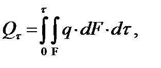 (9.5)
(9.5)
and the heat flux:
 (9.5")
If the value q is constant over the considered surface, then:
 (9.5")
Fourier law
This law sets the amount of heat flow when transferring heat through heat conduction. French scientist J. B. Fourier in 1807 he established that the density of the heat flux through an isothermal surface is proportional to the temperature gradient:
 (9.6)
(9.6)
The minus sign in (9.6) indicates that the heat flow is directed in the opposite direction to the temperature gradient (see Fig. 9.1.).
Heat flux density in an arbitrary direction l represents the projection onto this direction of the heat flux in the direction of the normal:

Coefficient of thermal conductivity
Coefficient λ , W/(m·K), in the Fourier law equation is numerically equal to the heat flux density when the temperature drops by one Kelvin (degree) per unit length. The thermal conductivity of various substances depends on their physical properties. For a certain body, the value of the thermal conductivity coefficient depends on the structure of the body, its volumetric weight, humidity, chemical composition, pressure, temperature. In technical calculations, the value λ are taken from reference tables, and it is necessary to ensure that the conditions for which the value of the thermal conductivity coefficient is given in the table correspond to the conditions of the calculated problem.
The coefficient of thermal conductivity depends especially strongly on temperature. For most materials, as experience shows, this dependence can be expressed by a linear formula:
 (9.7)
(9.7)
Where λ o - coefficient of thermal conductivity at 0 °C;
β - temperature coefficient.
Thermal conductivity coefficient of gases, and in particular vapors strongly depends on pressure. The numerical value of the thermal conductivity coefficient for various substances varies over a very wide range - from 425 W / (m K) for silver, to values of the order of 0.01 W / (m K) for gases. This is explained by the fact that the mechanism of heat transfer by thermal conduction in various physical environments different.
Metals have highest value thermal conductivity coefficient. The thermal conductivity of metals decreases with increasing temperature and decreases sharply in the presence of impurities and alloying elements. So, the thermal conductivity of pure copper is 390 W / (m K), and copper with traces of arsenic is 140 W / (m K). The thermal conductivity of pure iron is 70 W / (m K), steel with 0.5% carbon - 50 W / (m K), alloyed steel with 18% chromium and 9% nickel - only 16 W / (m K).
The dependence of the thermal conductivity of some metals on temperature is shown in fig. 9.2.
Gases have low thermal conductivity (of the order of 0.01...1 W/(m K)), which increases strongly with increasing temperature.
The thermal conductivity of liquids deteriorates with increasing temperature. The exception is water and glycerol. In general, the thermal conductivity of dropping liquids (water, oil, glycerin) is higher than that of gases, but lower than that of solids and lies in the range from 0.1 to 0.7 W / (m K).

Rice. 9.2. The effect of temperature on the thermal conductivity of metals