Technology and process of plasma spraying. Plasma-arc spraying Plasma spraying technology
So, what is the principle of plasma spraying? In all plasma spraying devices, the powder acquires temperature and speed in a stream of hot gas created by a plasmatron. In turn, a plasma torch or plasma generator is a device invented in the 1920s in which an electric arc burning between a cathode and an anode in a limited volume (nozzle) is inflated with an inert gas and creates a torch of high-temperature reducing flame.
Why is this principle so attractive for solving problems of thermal spraying? Precisely because the flame of the plasma torch is very hot and always strictly reducing; the presence of oxygen in the plasmatron is strictly prohibited due to the rapid, otherwise, destruction of electrode materials (the partial pressure of oxygen in plasma-forming gases is determined by their purity and should not be higher than 0.004%). The torch of the flame of the plasma torch, with its proper use, can not only restore the active metal surface from oxide films on the sprayed particles, but even clean the surface of the substrate from oxides. This opportunity is provided exclusively by the plasma spraying method.
With regard to plasma spraying, there are a number of prejudices among theorists and practitioners of thermal spraying, which, in most cases, are associated not with the process as such, but with a misunderstanding of the essence of the spraying process, design flaws of specific devices and their incorrect application. Let's discuss these prejudices:
1.“The plasma flame is too hot and therefore suitable only for sputtering refractory metal and oxide ceramic materials. Too high a temperature leads to evaporation of part of the powder and destruction of chromium and tungsten carbides.”
Indeed, the plasma temperature can reach 20,000°C or more, which is much higher than, for example, the temperature of an oxy-acetylene flame (about 3000°C). However, the flame temperature has very little to do with the temperature of the sprayed particles. Without delving into the physics of the interaction of hot gas with solid particles, we will only say that this interaction is very complex and depends on a large number of parameters, including not only the temperature of the gas, its speed, the length of the torch and the size of the particles, but also the chemical compositions of the gas and particles . In addition, it is not the absolute temperature of the flame, but its luminosity, that is decisive for the transfer of heat from the torch to the particles. For example, a hotter but almost invisible hydrogen-oxygen flame heats particles much worse than a cooler but brighter (due to glowing carbon nanoparticles) acetylene-oxygen flame. The luminosity of a plasma plume depends on the composition of the plasma-forming gas and on the size and composition of particles passing through it. It is interesting that in many cases this luminosity is less than that of an oxygen-acetylene flame and it has to be increased in various ways just to give the particles at least the minimum required temperature. Since the flame length of gas-flame devices also often exceeds the length of the plasma torch, a “paradox” results: coarse-grained metal powders heat up more strongly in powder flame spray devices than in more powerful and “hot” plasma spray devices.
2. “Particle velocity during plasma spraying is not sufficient to produce dense coatings.”
The flow rate of gas and particles in it is determined not by the principle of flame formation, but solely by the design of the device. Currently, there are industrial plasma spraying devices with a Laval nozzle that provide particles with supersonic speed.
3. “Only expensive vacuum plasma spraying units are suitable for metal spraying, while atmospheric plasma spraying units are unsuitable due to the oxidation of metal particles.”
Strange as it may seem, such a statement is heard quite often, even from people who are practically engaged in plasma spraying, especially in relation to MCrAlY coatings for gas turbine blades. In fact, in this statement there is a typical substitution of concepts: pure metal coatings from low-melting nickel alloys obtained by vacuum plasma deposition (VPS) are indeed better than atmospheric deposition (APS), but not because of the oxidation of particles in the plasma, but completely another reason, which will be discussed in the section on vacuum plasma deposition. The oxidation of metal particles in both of these methods occurs in the same way.
Atmospheric plasma spraying devices are no different from vacuum plasma spraying devices. The difference is not in the devices themselves, but in the way the deposition process is organized: atmospheric deposition is carried out in air, but with vacuum deposition both the plasmatron and the part being sprayed are in a vacuum chamber under vacuum. It is clear that atmospheric deposition is much more accessible and cheaper than vacuum deposition; moreover, for large parts, vacuum deposition becomes simply impossible due to the unrealistic size of the vacuum chamber. The plasmatrons themselves can be used for both atmospheric and vacuum deposition.
To more clearly explain the features of plasma spraying, let’s move on to consider the different designs that exist today.
Plasma spraying equipment
Plasma spraying devices come in a wide variety of designs. We will consider them from the most "traditional" to the most "advanced".
The most common devices are those with one cathode and one anode, and with the powder introduced outside a short nozzle, perpendicular to the flame axis.
The principle of operation of such devices is shown in the diagram (Figure 28):
Rice. 28. The principle of plasma spraying.
As can be seen from the diagram, the short nozzle of the plasma torch is also the anode. The powder is introduced outside the nozzle perpendicular to the flame axis, in close proximity to the arc.
The most popular device of this type is the 3MB plasmatron from Sulzer Metco, which, with minor modifications, has been around for more than 40 years. Figure 29 shows the current models of this series with a maximum power of 40 kW.
Rice. 29. Plasmatron 3MB.


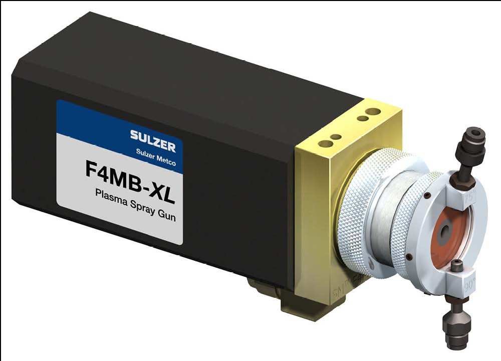
A slightly newer and more powerful (55 kW) single-cathode device is the F4 plasmatron, shown in Figure 30.
Rice. 30. Plasmatron F4.
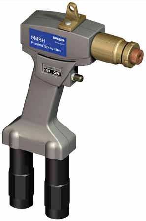
The 9MB device is one of the most powerful single-cathode plasmatrons of the traditional type (80 kW at a current of 1000 A and a voltage of 80 V) also produced by Sulzer Metco (Figure 31):
Rice. 31. Plasmatron 9MB

Traditional single-cathode plasmatrons from other companies differ little from Sulzer Metco plasmatrons: they all operate at a relatively low gas flow rate, low (< 100 В) напряжении и большом (до 1000 А) токе дуги. Ни один из традиционных плазматронов не позволяет достичь частицам скорости звука.
The advantage of plasmatrons with a low gas flow rate is the ability to impart a very high temperature to the particles (> 4000°C) due to the relatively long time they remain in the hot zone of the flame next to the arc. Such high particle temperatures make it possible to melt almost any ceramic and metal materials.
The development of plasma spraying technology in the last twenty years has been moving along the path of increasing particle speed. To give the particles greater speed, it is necessary to increase the pressure of the plasma-forming gases in front of the nozzle, which automatically leads to an increase in gas flow and an increase in arc voltage.
A modern, powerful (up to 85 kW, current up to 379 A, voltage up to 223 V) device with one cathode and anode is the 100HE plasmatron of the American company Progressive Technologies Inc., which, thanks to the high pressure and flow rate of plasma-forming gases, makes it possible to achieve particle velocities - close to the speed of sound (Figure 32):
Rice. 32. Plasmatron 100HE.

Due to the high speed of the plasma-forming gas, the residence time of particles in the hot zone of the flame and, accordingly, their temperature decreases. To counteract this, it is necessary to increase the arc power and use a large amount of hydrogen in the plasma-forming gas, which, thanks to the process of dissociation-association of molecules, lengthens the hot zone of the flame. Thus, the 100HE plasmatron realizes the temperature of particles with a size of 20-30 microns above 2300°C at a speed of about 250 m/sec, which makes it possible to spray coatings of Cr 3 C 2 - NiCr, Cr 2 O 3 and Al 2 O 3 with low porosity.
The second direction of development, in combination with an increase in gas consumption, is the division of one arc into three parts, which improves the stability and uniformity of the flame, reduces wear of the electrodes and increases the total flame power. A typical example of such a device is the latest TriplexPro TM -210 plasmatron from Sulzer Metco with one anode and three cathodes, a maximum power of 100 kW (Figure 33):
Rice. 33. Plasmatron TriplexPro TM.

1 – rear part of the body; 2 – anode stack; 3 – front part of the body; 4 – insulator; 5 - union nut; 6 – three cathodes in a ceramic block; 7 – anode stack element; 8 - plasma channel; 9 – nozzle with three powder nozzles.
Sulzer Metco's Triplex technology entered the thermal spray industry in the 1990s. These devices have, in comparison with plasmatrons with a single arc, a significantly longer service life and stability of deposition results. For many commercial powders, Triplex plasmatrons can also improve spraying productivity and efficiency while maintaining coating quality.
GTV GmbH has released, bypassing the Sulzer Metco patent for three-cathode plasmatrons, the GTV Delta device with one cathode and three anodes, which, in principle, is a degraded compilation of TriplexPro (Figure 34):
Rice. 34. Plasmatron GTV Delta.


The last, third direction of development is the abandonment of radial powder input in favor of a much more rational one - axial. The key design element of a plasmatron with axial powder injection, Convergens, was invented in 1994 by the American Lucian Bogdan Delcea.
Currently, there is only one similar device - the Axial III plasmatron, with a maximum power of 150 kW, produced by the Canadian company Mettech, which combines all three directions of development (high gas flow, three arcs and axial powder input). Plasma spraying units with the Axial III plasmatron are also manufactured and distributed by the German company Thermico GmbH.
Figures 35, 36 and 37 show the Axial III device itself and its design diagram:
Rice. 35. Plasmatron Axial III.

Rice. 36. View of the Axial III device from the nozzle side.

 Rice. 37. Schematic diagram of Axial III.
All modern plasma spraying installations are automatic, that is, the control of current sources, water cooling system and gas flow is regulated by a CNC system with visualization and saving of recipes on a computer. For example, the Axial III plasmatron is supplied by Thermico GmbH complete with a computerized control system that independently ignites arcs and enters the operating mode, selects spraying recipes, and controls all the main parameters: the flow of three plasma-forming gases (argon, nitrogen and hydrogen) , arc currents, water cooling system parameters. The same automatic system also controls the powder feeder.
Special mention needs to be made about the Thermico powder feeder. This, the most “advanced” device in the world today, allows not only to constantly regulate the mass flow of the powder and the flow of the carrier gas (nitrogen or argon), but also allows the use of fine-grained powders with poor flowability, unsuitable, for example, for Sulzer Metco feeders.
The author has personally worked with the Axial III plasmatron for a long time and can say from his own experience that despite some design flaws, this plasmatron is the most advanced thermal spraying device, combining the advantages of high-speed spraying with a high temperature strictly reducing flame. The main advantage of Axial III is the axial input of powder.
Advantages of axial powder input
Axial powder injection is a quantum leap in plasma spraying technology. The point here is not only that with axial input, powder losses are significantly reduced, but also that the possibility of spraying completely different powder materials that are unsuitable for radial input opens up. Since this aspect is fundamentally important for understanding the following sections, we will dwell on it in more detail.
So, what happens when powder is radially introduced into the flame jet at the nozzle exit? We list the disadvantages of such input:
- Only very narrow fraction powders are suitable for radial injection, for which it is necessary to accurately select the pressure of the carrier gas. What does this mean?: If the carrier gas pressure is insufficient, the powder particles will “bounce” off the flame jet; if the carrier gas pressure is too high, they will “shoot through” this flame; if the powder consists of particles of different sizes, then it is in principle impossible to select the “correct” pressure of the carrier gas: the smallest particles will always “bounce off”, and the largest ones will always “shoot through”, that is, neither of these particles will be in the sprayed coating there won’t be, but only some “average” particles. Fine-grained powders are especially difficult to introduce due to their increased dispersion by the carrier gas (a typical dust cloud around a torch).
- When introducing radial powder, it is impossible to use in the powder mixture not only particles of different sizes, but also different densities (different masses) for the same reason: heavier particles fly through the flame more easily than lighter ones. Thus, attempting to use complex powder mixtures will result in a distortion of the coating composition compared to the composition of the powder mixture.
- An increase in the velocity of plasma-forming gases complicates the radial injection of powder, since the ranges of required carrier gas pressures and particle size distributions are further narrowed. In practice, this means the following: the higher the flame speed, the lower the spraying efficiency during radial powder injection. It is impossible under any circumstances to introduce all the powder into the flame without loss.
- The location of the powder nozzles next to the hot flame zone causes their heating, which is compensated only by cooling by the gas carrying the powder. If the speed of the cooling gas is not enough for cooling, then powder particles can stick to the edges of the nozzle opening, forming sagging. The stuck pieces periodically come off the nozzle, fall into the flame and cause a characteristic defect - “spitting”, leading to the formation of coarse porous inclusions in the coating. Since the flow rate of the carrier gas is strictly related to the flame parameters (see point 1), a problem arises: for some powders there are simply no parameters that eliminate the “spitting” effect, especially if these powders are low-melting and/or fine-grained.
Switching to axial injection of powder allows you to completely get rid of the above problems:
- Carrier gas pressure and velocity are no longer tied to flame and powder parameters. The only condition is that the pressure of the carrier gas must be slightly higher than the pressure of the plasma-forming gas in the nozzle at the point where the powder is introduced. Due to the axial input, any powder is completely captured by the flame.
- It is always possible to select a pressure of the carrier gas at which “spitting” associated with powder sticking to the edge of the hole in the powder nozzle will not occur.
- It is possible to use powder mixtures of any complexity and fractional composition. Particles of different sizes will acquire different speeds and temperatures, but all will eventually take part in the formation of the coating. The fact that small particles become significantly hotter than large ones when axially introduced into a plasma flame opens up new possibilities for the design of powder mixtures. The main part of this book is devoted to the creation of such polyfractional compositions.
The author was very fortunate to have had an Axial III plasmatron with axial powder injection at his disposal for many years. If not for this, the creation of new multicomponent coatings would simply be impossible.
Summary table of thermal spray devices
To generalize, directly compare and systematize all thermal spraying methods, let’s compare the properties of typical devices, as well as their approximate prices in one table (Table 2):
Table 2. Comparison of Thermal Spray Devices.
| Properties and characteristics | * Thermal spray methods | |||||||
| 1 | 2 | 3 | 4 | 5 | 6 | 7 | 8 | |
| Using powder or wire | wire | powder | wire | powder | powder | powder | wire | powder |
| Maximum speed sprayed particles, m/s | 100 | 50 | 200 | 800 | 1200 | 1000 | 100 | 400 |
| Maximum temperature sprayed particles, °C | 2800 | 2500 | 1700 | 1500 | 600 | 1200 | > 4000 | > 4000 |
| The size of the particles forming coating, microns | 0,1 – 1000 | 10 – 150 | 0,1 – 1000 | 10 – 100 | 10 – 100 | 10 – 100 | 0,1 – 1000 | 1 – 50 |
| Spraying efficiency by sprayed material | — | + | — | +++ | +++ | +++ | — | ++ |
| Sputtering efficiency by consumption | – | +++ | — | — | — | — | ++ | – |
| Minimum porosity coating, vol.% | 10-15 | 10-25 | 5-10 | 2-3 | < 1 | < 1 | 5-10 | 0,5-3 |
| Thermal power devices, kW | 10-30 | 10-50 | 30-100 | 50-250 | 30-85 | < 20 | 20-150 | 25-150 |
| Performance spraying, kg/hour | 2-5 | 5-10 | 2-5 | 5-10 | 10-20 | < 1 | 10-30 | 2-5 |
| Prevalence commercial devices and spare parts on the world market | A lot of devices | A lot of devices | Few devices | A lot of devices | Few devices | No devices | A lot of devices | A lot of devices |
| Device mobility | +++ | +++ | – | – | +++ for - for others | — | +++ | – for APS |
| Device noise | — | +++ | — | — | — | — | — | — |
| Emission of vapors and fine dust | — | ++ | — | ++ | +++ | ++ | — | – |
| Price of individual devices, € | 2.000- | 2.000- | 10.000- | 10.000- | 10.000- | No | 10.000- | 5.000- |
| Price of automated installations without peripherals, € | No | 30.000- | No | 100.000- | 100.000- | No | No | 100.000- |
| Price of automated installations with periphery “under key": soundproof cabin, filter-ventilation installation, robot, etc., € | No | 100.000- | No | 200.000- | 200.000- | No | No | 200.000- |
| Comparative Cost operation taking into account consumables materials (except powders and wires), device life and spare parts, | 10-15 | 5-15 | 30-60 | 40-100 | 40-100 | > 100 | 5-30 | 30-150 |
* Numbering of methods:
- Wire flame spraying
- Flame powder spraying
- Supersonic flame spraying with wire
- Supersonic flame powder spraying (HVOF and HVAF)
- Cold powder spraying
- Detonation powder spraying
- Electric arc spraying with wire
- Plasma powder spraying (APS and VPS)
Plasma surfacing is an innovative method of applying special coatings with a high wear resistance to the surface of worn products. It is performed to restore machine parts and mechanisms, as well as during their production.
1 Plasma surfacing - general information about the technique and its advantages
A number of components and mechanisms of various devices and machines today operate in difficult conditions that require products to meet several requirements at once. They are often required to withstand the influence of aggressive chemical environments and elevated temperatures, and at the same time maintain their high strength characteristics.
It is almost impossible to make such units from any one metal or other material. And from a financial point of view, it is not practical to implement such a complex production process.
It is much more reasonable and profitable to produce such products from one, maximum durable material, and then apply certain protective coatings to them - wear-resistant, heat-resistant, acid-resistant, and so on.
As such “protection”, you can use non-metallic and metallic coatings, which differ from each other in their composition. Such spraying makes it possible to give products the necessary dielectric, thermal, physical and other characteristics. One of the most effective and at the same time universal modern methods of coating materials with a protective layer is spraying and surfacing with a plasma arc.
The essence of using plasma is quite simple. For coating, material is used in the form of wire or granulated fine powder, which is fed into a plasma jet, where it is first heated and then melted. It is in the molten state that the protective material falls on the part subjected to surfacing. At the same time, its continuous heating occurs.
The advantages of this technology are:
- the plasma flow allows you to apply materials of different parameters, and in several layers (due to this, the metal can be treated with different coatings, each of which has its own protective features);
- the energy properties of the plasma arc can be adjusted within wide limits, since it is considered the most flexible heat source;
- the plasma flow is characterized by a very high temperature, due to which it easily melts even those materials that are described by increased refractoriness;
- Geometric parameters and shape of the part for surfacing do not limit the technical capabilities of the plasma method and do not reduce its effectiveness.
Based on this, we can conclude that neither vacuum, nor galvanic, nor any other variant of deposition can be compared in terms of efficiency with plasma. Most often it is used for:

- strengthening products that are subject to constant high loads;
- protection against wear and rust of shut-off and control and shut-off elements (sputtering of metal with the help of plasma significantly increases their durability);
- protection from the negative effects of high temperatures, which cause premature wear of products used by glass factories.
2 The technology of the described surfacing and its subtleties
Plasma surfacing of metal is performed using two technologies:
- a rod, wire or tape is introduced into the stream (they act as a filler material);
- A powder mixture is fed into the jet, which is captured and transferred to the surface of the welded product by gas.

The plasma jet can have different configurations. According to this indicator, it is divided into three types:
- Closed jet. With its help, metal deposition, metallization and hardening are most often performed. The arc in this case is characterized by a relatively low intensity of the flame flow, which is caused by a high level of heat transfer to the atmosphere. In the described arrangement, the anode is either the burner channel or its nozzle.
- Open jet. With this arrangement, the part heats up much more; the anode is the rod or the workpiece itself. An open jet is recommended for applying protective layers or for cutting material.
- Combined option. A layout designed specifically for plasma-powder surfacing. With this option, two arcs are ignited at the same time, and the anode is connected to the burner nozzle and to the welded product.

For any arrangement, the gases used to form the flame are oxygen, argon, air, helium, hydrogen or nitrogen. Experts say that helium and argon provide the highest quality deposition and surfacing of metal.
3 Combined plasma torch for surfacing
Plasma-powder surfacing at most modern enterprises is carried out in combined units. In them, metal filler powder is melted between a torch nozzle and a tungsten electrode. And while the arc burns between the part and the electrode, heating of the surface of the welded product begins. Due to this, high-quality and rapid fusion of the base and filler metal occurs.
The combined plasma torch provides a low content of the deposited base material in the composition, as well as the smallest depth of its penetration. It is these facts that are recognized as the main technological advantage of surfacing using a plasma jet.

The surface to be deposited is protected from the harmful influence of ambient air by inert gas. It enters the nozzle (external) of the installation and reliably protects the arc, surrounding it. A transport gas with inert characteristics is also used to supply the powder mixture for the additive. It comes from a special feeder.
In general, a standard plasma torch of a combined type of action, in which metal spraying and surfacing is carried out, consists of the following parts:

- two power sources (one powers the “indirect” arc, the other – the “direct”);
- feeder for mixture;
- resistance (ballast);
- hole where gas is supplied;
- nozzle;
- oscillator;
- burner body;
- pipe for supplying gas carrying the powder composition.
4 Main features of metal surfacing using plasma technology
The maximum performance of the plasma torch is noted when a current-carrying wire additive is used. The arc in this case burns between this wire (it is the anode) and the cathode of the unit. The described method slightly melts the base material. But it does not make it possible to create a uniform and thin surfacing layer.

If powder is used, spraying and surfacing make it possible to obtain the specified thin layer with maximum wear resistance and heat resistance. Typically, the components of the powder mixture for surfacing are cobalt and nickel. After using such powders, the surface of the part does not need to be further processed, since its protective layer does not have any defects.
Plasma spraying, as compared to hardfacing, is described by a higher plasma jet velocity and a denser heat flux. This fact is due to the fact that metals and compounds with a high level of refractoriness (borides, silicides, tantalum, carbides, tungsten, zirconium, magnesium and aluminum oxides) are most often used during spraying.

We add that the surfacing method considered in the article in terms of its technical characteristics (range of operating voltages and currents, inert gas consumption, and so on) is not much different from. And specialists have mastered this type of welding activities today to perfection.
This is a progressive method of coating, in which the melting and transfer of material to the surface to be restored is carried out by a plasma jet. Plasma is a highly ionized state of gas when the concentration of electrons and negative ions is equal to the concentration of positively charged ions. A plasma jet is obtained by passing a plasma-forming gas through an electric arc when it is powered by a DC source with a voltage of 80-100 V.
The transition of the gas into an ionized state and its disintegration into atoms is accompanied by the absorption of a significant amount of energy, which is released when the plasma is cooled as a result of its interaction with the environment and the sprayed part. This causes a high temperature of the plasma jet, which depends on the current strength, type and flow rate of gas. The plasma-forming gas is usually argon or nitrogen and, less commonly, hydrogen or helium. When using argon, the plasma temperature is 15,000-30,000 °C, and nitrogen - 10,000-15,000 °C. When choosing a gas, it should be taken into account that nitrogen is cheaper and less scarce than argon, but to ignite an electric arc in it, a significantly higher voltage is required, which determines increased requirements for electrical safety. Therefore, sometimes when igniting an arc, argon is used, for which the excitation and arc burning voltage is lower, and nitrogen is used in the sputtering process.
The coating is formed due to the fact that the applied material entering the plasma jet melts and is transferred by a stream of hot gas to the surface of the part. The flight speed of metal particles is 150-200 m/s at a distance from the nozzle to the surface of the part of 50-80 mm. Due to the higher temperature of the applied material and higher flight speed, the strength of the connection between the plasma coating and the part is higher than with other metallization methods.
High temperature and high power compared to other heat sources are the main differences and advantages of plasma metallization, providing a significant increase in process productivity, the ability to melt and deposit any heat-resistant and wear-resistant materials, including hard alloys and composite materials, as well as oxides, borides, nitrides and etc., in various combinations. Thanks to this, it is possible to form multilayer coatings with various properties (wear-resistant, easily break-in, heat-resistant, etc.). The highest quality coatings are obtained by using self-fluxing surfacing materials.
The density, structure and physical and mechanical properties of plasma coatings depend on the applied material, dispersion, temperature and collision rate of the transferred particles with the part being restored. The last two parameters are provided by controlling the plasma jet. The properties of plasma coatings increase significantly during their subsequent melting. Such coatings are effective under impact and high contact loads.
The principle of operation and design of the plasma torch is illustrated in Fig. 4.51. A plasma jet is obtained by passing plasma-forming gas 7 through an electric arc created between the tungsten cathode 2 and the copper anode 4 when a current source is connected to them.
The cathode and anode are separated from each other by an insulator 3 and are continuously cooled by liquid b (preferably distilled water). The anode is made in the form of a nozzle, the design of which ensures compression and a certain direction of the plasma jet. The compression is also facilitated by the electromagnetic field that arises around the jet. Therefore, the ionized plasma-forming gas leaves the plasmatron nozzle in the form of a jet of small cross-section, which provides a high concentration of thermal energy.
Rice. 4.51. Scheme of the plasma spraying process: 1 - powder dispenser; 2- cathode; 3 - insulating gasket; 4 - anode; 5 - transport gas; 6 - coolant; 7 - plasma-forming gas
The applied materials are used in the form of granular powders with a particle size of 50-200 microns, cords or wire. The powder can be fed into the plasma jet together with the plasma-forming gas or from the dispenser 1 with the transport gas 5 (nitrogen) into the nozzle of the gas torch, and a wire or cord is inserted into the plasma jet below the nozzle of the plasma torch. Before use, the powder should be dried and calcined to reduce porosity and increase the adhesion of the coating to the part.
Protection of the plasma jet and the molten metal particles contained in it from interaction with air can be carried out by a flow of inert gas, which should surround the plasma jet. For this purpose, an additional nozzle is provided in the plasmatron, concentrically with the main one, through which inert gas is supplied. Thanks to it, oxidation, nitriding and decarbonization of the sprayed material are eliminated.
In the example considered, the power source is connected to the electrodes of the plasma torch (closed connection circuit), so the electric arc serves only to create a plasma jet. When using the applied material in the form of a wire, the power source can also be connected to it. In this case, in addition to the plasma jet, a plasma arc is formed, which also participates in the melting of the rod, due to which the power of the plasma torch increases significantly
Modern plasma surfacing installations have electronic systems for regulating process parameters and are equipped with manipulators and robots. This increases the productivity and quality of the spraying process, and improves the working conditions of operating personnel.
The main differences between plasma metallization and other melting methods are higher temperature and greater power, which provides a significant increase in process productivity and the ability to apply and melt any heat-resistant and wear-resistant materials (Fig. 4.8). For plasma spraying, argon and nitrogen gases are used to provide the jet temperature. For plasma metallization, UPU and UMN installations are widely used, the set of which includes a rotator, a protective chamber, a powder dispenser, a power source and a control panel.
The main part of the installation is the plasmatron, the service life of which is determined by the durability of the nozzle. The operating period of the plasma torch is short, so its wearing parts are made replaceable. The current sources are welding generators PSO-500 or rectifiers I PN-160/600.
Rice. 4.8. Scheme of the plasma spraying process:
1 - powder dispenser; 2 - cathode; 3 - insulating gasket; 4 - anode; 5 - transport gas; 6 - coolant; 7 - plasma-forming gas
Argon or less scarce and cheaper nitrogen is used as a plasma-forming gas. However, igniting an arc in a nitrogen environment is more difficult and requires significantly higher voltage, which poses a danger to operating personnel. A method is used in which an arc is ignited in an argon environment with a lower excitation and arc burning voltage, and then switched to nitrogen. The plasma-forming gas is ionized and leaves the plasmatron nozzle in the form of a jet of small cross-section. The compression is facilitated by the walls of the nozzle channel and the electromagnetic field that arises around the jet. The temperature of the plasma jet depends on the current strength, type and flow rate of gas and varies from 10,000 to 30,000 °C; gas flow speed is 100-1500 m/s. Argon plasma has a temperature of 15,000-30,000 °C, nitrogen plasma - 10,000-15,000 °C.
In plasma metallization, granulated powder with a particle size of 50-200 microns is used as the applied material. The powder is fed into the arc zone by a transport gas (nitrogen), melted and transferred to the part. The flight speed of powder particles is 150-200 m/s, the distance from the nozzle to the surface of the part is 50-80 mm. Due to the higher temperature of the applied material and the higher flight speed of the sprayed particles, the strength of the connection between the coating and the part in this method is higher than with other metallization methods.
Plasma metallization, which occurs at a high temperature of the plasma jet, makes it possible to apply any material
materials, including the most wear-resistant ones, but this raises the problem of subsequent processing of super-hard and wear-resistant materials.
The use of pulsed laser radiation, the duration of which is milliseconds, makes it possible to obtain minimal thermally affected zones that do not exceed several tens of microns. Minimum volumes of melt and minimal heat input into the part being welded make it possible to reduce longitudinal and transverse deformations and thereby maintain the precision dimensions of the part within the tolerance range of several microns. The precision of guidance and local action of the laser beam allows welding strictly defined geometric areas of the part, providing a minimum allowance for machining, which is 0.2-0.5 mm. Since during pulsed laser cladding the heat-affected zones are very small, the substrate remains practically cold, and the cooling rate of the liquid phase of the metal melt reaches 102-103 °C/s. Under these conditions, an auto-hardening process takes place, which leads to the formation of an extremely finely dispersed structure with increased wear resistance.
When compared, almost all of the fundamental technical differences between electric arc cladding and pulsed laser cladding technologies are a consequence of the fact that the arc is a concentrated welding energy source, and the laser beam is a highly concentrated energy source. Pulsed laser surfacing, compared to electric arc surfacing, is characterized by minimal volumes of melt, heat-affected zones and, accordingly, significantly lower transverse and longitudinal shrinkage.
After electric arc surfacing, allowances can reach several millimeters, which necessitates subsequent machining. The use of an electric arc as an energy source is accompanied by its forceful effect on the liquid phase of the metal melt, resulting in the formation of undercuts that do not occur during laser cladding. Electric arc surfacing requires preliminary and concomitant" heating of the welding areas and subsequent heat treatment and "and type from laser surfacing.
Laser surfacing technology can be used to restore worn-out molds, dies and eliminate various defects formed during the manufacturing process of molds and dies. Types of defects eliminated using laser cladding: HRC hardness test sites, cracks, nicks, scuffs, cavities and pores, deep cracks, adhesive bonding sites. The technological process of laser surfacing is a simultaneous supply of laser radiation and filler wire to the defect site in an inert gas environment. The filler material, melting, fills the defect site. After laser surfacing, minimal mechanical processing is required compared to traditional surfacing methods. The high accuracy of pointing the laser beam at the location of the defect, the locality of the action of laser radiation makes it possible to fuse strictly defined areas of defective parts (Fig. 4.9).
![]()
 The short duration of the process, the duration of the laser pulse of several milliseconds, as well as the precise dosage of energy ensure minimal heat-affected zones and the absence of part wear. Laser surfacing can significantly reduce the labor intensity of tooling repairs and, as a consequence, the cost by eliminating from the process preheating, subsequent heat treatment, and the need to remove the chromium coating from the surface and its subsequent application if the part is chrome-plated. The advantages of laser cladding are listed in table. 4.2.
To prevent oxidation of the molten metal, the surfacing zone is protected with inert gases, for example, a mixture of argon and helium. For surfacing large-sized components (up to several meters in length), solid-state laser systems equipped with fiber optic systems are used. A technology has been developed for eliminating defects in the form of hot and cold non-through cracks formed during electric arc welding with stick electrodes using pulsed laser radiation from solid-state lasers.
Welding several cracks using pulsed laser radiation makes it possible to implement the so-called “cold” welding mode, in which the weld in the repaired area does not heat up, which allows maintaining the mechanical strength of the welded joint and avoiding tempering of the metal in the weld.
The use of a fiber optic system several meters long allows repairs to be carried out in the most difficult-to-reach places. This technology can be used to eliminate various defects formed during electric arc welding - cracks, both cold and hot, cavities, craters, fistulas, undercuts.
Due to the nature and operating conditions, the lateral surface of high-pressure turbine blades is subject to microdamage from mechanical, chemical and thermal influences. Damageability analysis shows that about 70% of their total number are parts with surface defects up to 0.4-2.0 mm deep. The use of fiber optic systems for delivering a laser beam to the defect site opens up the possibility of repairing a turbine blade without dismantling it. The size of the thermally affected zone does not exceed 15 µm. The structure of the deposited layer is finely dispersed.

Rice. 4.11. Cross section at the location of the unsoldered tube of the refrigerator section
 |
|||
Rice. 4.12. Grinding of the defect site processed in welding-soldering mode
During the manufacturing process of water sections, defects in the form of missing solders may occur. A technology has been developed to eliminate section leaks using pulsed laser soldering-welding (Fig. 4.11 and 4.12).
To eliminate leaks in a soldered seam, pulsed laser radiation from a solid-state laser is used. A television system built into the laser emitter using target designation based on a He - Ne (helium - neon) laser allows you to accurately direct the laser beam to the defect site. Equipping the laser with a fiber optic system allows you to eliminate defects in hard-to-reach places and make a quick transition from one defect to another.
Plasma spraying (or, in other words, diffusion metallization) is an effective way to change the physical and mechanical properties, as well as the structure of the main surface. Therefore, it is often used for decorative purposes and to increase the durability of the final product.
The principle of plasma spraying
Like traditional surface coating methods, diffusion metallization involves the deposition of a layer of another metal or alloy on the metal surface, which has the properties necessary for subsequent use of the part - the desired color, corrosion resistance, hardness. The differences are as follows:
- High-temperature (5000 - 6000 °C) plasma significantly speeds up the coating process, which can take a fraction of a second.
- During diffusion metallization in a plasma jet, chemical elements from the gas where the treatment is carried out can also diffuse into the surface layers of the metal. Thus, by adjusting the chemical composition of the gas, it is possible to achieve a combined surface saturation of the metal with atoms of the desired elements.
- The uniformity of temperature and pressure inside the plasma jet ensures high quality of the final coatings, which is very difficult to achieve with traditional metallization methods.
- Plasma spraying is characterized by an extremely short process time. As a result, not only productivity increases, but also overheating, oxidation, and other undesirable surface phenomena are eliminated.
Working installations for the implementation of the process
Since an electric discharge is most often used to initiate high-temperature plasma - arc, spark or pulse - the equipment used for this sputtering method includes:
- Source of discharge creation: high-frequency generator or welding converter;
- A working sealed chamber where the workpiece to be metallized is placed;
- A reservoir for gas in the atmosphere of which high-temperature plasma will be formed;
- A pump or vacuum unit that provides the necessary pressure to pump the working medium or to create the required vacuum;
- Process control systems.
The operation of a plasma torch that performs plasma spraying occurs as follows. The sprayed part is fixed in a sealed chamber, after which an electric discharge is excited between the surfaces of the working electrode (which includes the sprayed elements) and the workpiece. At the same time, a liquid or gaseous medium is pumped through the working area with the required pressure. Its purpose is to compress the discharge zone, thereby increasing the volumetric density of its thermal power. Highly concentrated plasma provides dimensional evaporation of the electrode metal and simultaneously initiates pyrolysis of the environment surrounding the workpiece. As a result, a layer of the desired chemical composition is formed on the surface. By changing the discharge characteristics - current, voltage, pressure - you can control the thickness and structure of the sprayed coating.
The process of diffusion metallization in a vacuum occurs similarly, except that plasma compression occurs due to the difference in pressure inside and outside its column.
Technological equipment, consumables
The choice of electrode material depends on the purpose of the spraying and the type of metal being processed. For example, for hardening dies, the most effective electrodes are made of iron-nickel alloys, which are additionally alloyed with elements such as chromium, boron, and silicon. Chrome increases the wear resistance of the coating, boron increases the hardness, and silicon increases the density of the finishing coating.
When metallizing for decorative purposes, the main criterion for choosing the metal of the working electrode is the configuration of the surface to be sprayed, as well as its appearance. Copper deposition, for example, is carried out using electrodes made of electrical copper M1.
An important structural component of the process is the composition of the medium. For example, if it is necessary to obtain highly resistant nitrides and carbides in the sprayed layer, organic media containing carbon or nitrogen must be present in the gas.
Subsequent processing of the finished coating
Due to the nature of the process, the density of the sprayed layer and the strength of its adhesion to the base metal are not always sufficient to ensure the durability of the coating. Therefore, often after processing, the part is subjected to subsequent surface melting using an oxygen-acetylene flame, or in thermal furnaces. As a result, the coating density increases several times. After this, the product is ground and polished using carbide tools.
Taking into account the subsequent finishing of the product, the thickness of the metal layer after processing is taken to be at least 0.8 - 0.9 mm.
To give the part final strength properties, it is hardened and tempered using technological conditions recommended for the base metal.
Plasma spraying increases heat resistance, wear resistance and hardness of products, increases their ability to resist corrosion processes, and spraying for decorative purposes significantly improves the appearance of parts.
The limitations of diffusion plasma spraying technology are the excessive complexity of the workpiece configuration, as well as the relative complexity of the installations used.
If the requirements for the uniformity of the resulting layer are not high, simpler installations that are structurally reminiscent of semi-automatic welding machines can be used. In this case, plasma spraying is carried out in an air bubble, which is formed when the treatment area is blown by a compressor. The electrodes, which contain the sprayed metal, move sequentially along the contour of the product. To improve the adhesion of the sprayed metal to the base, filler material is also introduced into the spraying zone.