kv antenna. Homemade trap dipole: theory and practice Dipole for 80 meters with symmetrical power supply
In radio communication, antennas are given a central place, in order to ensure its best, radio communication, action, antennas should be given the closest attention. In essence, it is the antenna that carries out the radio transmission process itself. Indeed, the transmitting antenna, fed by a high-frequency current from the transmitter, converts this current into radio waves and radiates them in the right direction. The receiving antenna, on the other hand, performs the reverse conversion - radio waves into a high-frequency current, and already the radio receiver performs further conversions of the received signal.
For radio amateurs, where you always want more power, to communicate with possibly more distant interesting correspondents, there is a maxim - the best amplifier (HF), this is an antenna.
To this club of interests, while I belong somewhat indirectly. There is no amateur radio call sign, but it's interesting! You can’t work for the program, but listen, get an idea, that’s it, please. Actually, this occupation is called radio surveillance. At the same time, it is quite possible to exchange with a radio amateur whom you heard on the air, receipt cards of the established sample, in the slang of radio amateurs QSL. Acknowledgments of reception are also welcomed by many HF broadcasting stations, sometimes encouraging such activity with small souvenirs with radio station logos - it is important for them to know the conditions for receiving their broadcasts in different points peace.
The observer's radio receiver can be quite simple, at least at first. The antenna, on the other hand, is a construction that is unlike more cumbersome and expensive, and the lower the frequency, the more cumbersome and expensive - everything is tied to the wavelength.
The bulkiness of antenna structures is largely due to the fact that at a low suspension height, antennas, especially for low-frequency bands - 160, 80.40 m, work poorly. So it is the masts with guy wires that provide them with bulkiness, and lengths of tens, sometimes hundreds of meters. In a word, not particularly miniature pieces. It would be nice to have a separate field for them near the house. Well, that's how lucky.
So, an asymmetric dipole.

Above is a diagram of several options. The MMANA mentioned there is a program for modeling antennas.
The conditions on the ground turned out to be such that the variant of two parts 55 and 29m comfortably fit. It stopped on it.
A few words about the radiation pattern.
The antenna has 4 petals, "pressed" to the canvas. The higher the frequency - the more they "cling" to the antenna. But truth and empowerment have more. So on this principle
it is possible to build completely directional antennas, which, however, have, in contrast to the “correct” ones, not a particularly high gain. So you need to place this antenna taking into account its DN.
The antenna on all ranges indicated on the diagram has SWR (standing wave ratio, a very important parameter for the antenna) within reasonable limits for HF.
To match an asymmetric dipole - aka Windom - you need a SPTDL (broadband transformer on long lines). Behind this terrible name lies a relatively simple design.

Looks like this.

So what has been done.
First of all, I decided on strategic issues.
I made sure that the basic materials are available, mainly, of course, a suitable wire for the antenna web in the proper amount.
Decided on the place of suspension and "masts". The recommended hanging height is 10m. My wooden mast, standing on the roof of the firewood shed, turned in the spring with falling frozen snow - I didn’t wait, it’s not a pity, I had to clean it up. It was decided so far to hook one side of the roof ridge, while the height will be about 7m. Not much, of course, but cheap and cheerful. It was convenient to hang the second side on a linden tree standing in front of the house. The height there turned out to be 13 ... 14m.
What was used.
Tools.
Soldering iron, of course, with accessories. Power, watts, that way forty. Tool for radio installation and small metalwork. Whatever is boring. A powerful electric drill with a long drill bit for wood was very useful - let the coaxial drop cable through the wall. Definitely an extension cord. Used hot glue. Work at height is ahead - it is worth taking care of suitable strong ladders. It helps a lot to feel more confident, away from the ground, a safety belt - like fitters on poles. Climbing up, of course, is not very convenient, but you can already work “there”, with both hands and without much concern.
Materials.
The most important thing is the material for the canvas. I used a "vole" - a field telephone wire.
Coaxial cable to reduce how much you need.
A few radio components, a capacitor and resistors according to the scheme. Two identical ferrite tubes from high-frequency filters on cables. Ties and fasteners for thin wire. small block(roller) with ear-mount. A suitable plastic box for the transformer. Ceramic insulators for the antenna. Nylon rope of suitable thickness.
What was done.
First of all, I measured (seven times) pieces of wire for the canvas. With some margin. Cut off (once).
I took up the manufacture of a transformer in a box.
Picked up ferrite tubes for the magnetic circuit. It is made of two identical ferrite tubes from filters on monitor cables. Now old CRT monitors are simply thrown away and it is not particularly difficult to find "tails" from them. You can ask around with friends, for sure, someone may be gathering dust in attics or in the garage. Good luck if there are familiar system administrators. In the end, in our time, when switching power supplies are everywhere and the struggle for electromagnetic compatibility is serious, there can be many filters on cables, moreover, such ferrite products are vulgarly sold in electronic component stores.
Matched identical tubes are folded in the manner of binoculars and fastened with several layers of adhesive tape. The winding is made of a mounting wire of the maximum possible cross section, such that the entire winding fits in the windows of the magnetic circuit. The first time it did not work out and I had to proceed by trial and error, fortunately, there are very few turns. In my case, there was no suitable section at hand and I had to wind two wires at the same time, making sure that they did not overlap in the process.
To obtain a secondary winding - we make two turns with two wires folded together, then pull each end of the secondary winding back (in reverse side tube), we get three turns with a midpoint.

From a piece of rather thick textolite, a central insulator is made. There are special ceramic ones specifically for antennas, of course it is better to use them. Since all laminates are porous and, as a result, very hygroscopic, so that the antenna parameters do not “float”, the insulator should be thoroughly impregnated with varnish. I applied oil glyptal, yacht.

The ends of the wires are cleaned of insulation, passed through the holes several times and thoroughly soldered with zinc chloride (soldering acid flux) so that the steel veins are also soldered. Soldering points are very thoroughly washed with water from flux residues. It can be seen that the ends of the wires are pre-threaded into the holes of the box where the transformer will sit, otherwise you will then have to thread all 55 and 29 meters into the same holes.
I soldered the corresponding transformer leads to the cutting points, shortening these leads to a minimum. Before each action, do not forget to try on the box, so that everything fits later.

From a piece of textolite from an old printed circuit board, I sawed a circle to the bottom of the box, there are two rows of holes in it. Through these holes, a coaxial drop cable is attached with a bandage of thick synthetic threads. The one in the photo is far from the best in this application. This is a television with foam insulation of the central core, the “mono” core itself, for screw-on TV connectors. But there was a trophy bay available. Applied it. Circle and bandage, well impregnated with varnish and dried. The end of the cable is pre-cut.

The rest of the elements are soldered, the resistor is made up of four. Everything is filled with hot-melt adhesive, probably in vain - it turned out hard.

Ready-made transformer in the house, with "outputs".

In the meantime, a fastening to the ridge was made - there are two boards at the very top. Long strips of roofing steel, stainless steel eyelet 1.5mm. The ends of the rings are welded. On the strips along a row of six holes for self-tapping screws - distribute the load.

Block prepared.

I didn’t get ceramic antenna “nuts”, I used vulgar rollers from old wiring, fortunately, they are still found in old village houses for demolition. Three pieces on each edge - the better the antenna is isolated from the "ground", the weaker signals it can receive.
The applied field wire is interwoven with steel strands and can withstand stretching well. In addition, it is intended for laying in the open air, which is also quite suitable for our case. Radio amateurs quite often make canvases of wire antennas from it, and the wire has proven itself well. Some experience of its specific application has been accumulated, which first of all says that you should not bend the wire too much - the insulation bursts in the cold, moisture gets on the cores and they begin to oxidize, in that place, after a while, the wire breaks.
Antenna is a radio engineering device that converts radio wave energy into an electrical signal and vice versa. Antennas differ in type, purpose, frequency range, radiation pattern, etc. In this article, we will look at the construction of the most common amateur radio antennas. The best amplifier is the antenna!
Experienced radio amateurs know this very well and spare no time and money to improve their antennas. But it's hard to even imagine how much time, effort and money it took the "hot Finnish guys" with OH8X to build such a "monster". Three elements at 160m and four full size elements at 80m. Moreover, since the dimensions of the elements of the wave channel are equal to half the wavelength, then each of the four elements is forty meters long. And all this at an altitude of 100 meters. The weight of this structure is also impressive - almost 40 tons.
But "hot" guys are not only in Finland. Antenna RN6BN, and this 
an in-phase array of 65 fifteen-element wave channels at 144 MHz is no less impressive. Or the UN7L antenna. Certainly not a "monster", but most radio amateurs can only dream of such. 
Well, for those who are the happy owner of a car and dream of installing a VHF antenna on it. As they say, simple but tasteful 
All these and similar antennas require painstaking tuning, huge financial investments, and, most importantly, a lot of experience and knowledge. It should be noted that a simple but well-adjusted antenna, such as a dipole, will be much more effective than a multi-element, but not tuned antenna. A tuned resonant antenna will allow you to listen and make radio communications with very weak and distant stations. A bad antenna will negate all your efforts to buy or build a receiver / transceiver
Now consider the antennas themselves. Let's start with the simplest and go to the highest quality.
Antenna "Inclined Beam"
Her canvas is a piece of copper wire, which is fixed at one end to a tree, a lamppost, the roof of a neighboring house, and the other side is connected to a receiver / transceiver. Advantages: - simple design. 
Disadvantages: - weak gain, highly susceptible to urban noise, requires coordination with the transceiver / receiver. For the manufacture of the antenna web, any copper wire is suitable - single-core, stranded, insulated and without. Any thickness, but - "so as not to break" from its weight, tension and wind. On average, the cross section is 2.5-6 sq. mm. A untwisted army telephone wire is also suitable. The antenna is multi-band, but the number of bands on which it can be used depends on its size.
The length of the antenna web is determined for the lowest frequency range using the formula 300/2*f, where f is the average frequency of the range. In particular, for the 80-meter range, this is 42.6 meters. An antenna with such gaps will work decently on 3.5, 7.0, 14.0, 21.0 and 28.0 MHz. By halving the dimensions, we get everything the same, but without 3.5 MHz. It is clear that the size is approximate, since the length of the canvas depends on the surrounding objects, the height of the suspension, and whether the wire is insulated or not. Accurate dimensions can only be obtained after careful tuning.
It should be remembered that the antenna wire cannot be tied directly to the supports. It is necessary to install several insulators at the end of the antenna web. Ideal insulators - "nut type": 
Why insulators are needed should be clear from their very name. They insulate the antenna sheet electrically from the tree, pole and other structures to which you will mount the antenna. If nut insulators are not found, you can make homemade ones from any durable dielectric material: - plastic, textolite, plexiglass, pvc tubes, etc. 
Wood and derivatives (chipboard, fiberboard, etc.) cannot be used. At the ends of the antenna there should be 2 - 3 insulators, with a distance of 30-50cm from each other. As you know, a half-wave vibrator powered from the end, which is a resonant (half-wave) inclined beam, has a large resistance and a matching device is needed to connect it to a transceiver or receiver with a low-impedance input. Various matching devices will be discussed in a separate article.
Antenna "Dipole"
This is already a more serious antenna than an inclined beam. A dipole is two pieces of wire in the center of which a coaxial drop cable is connected to the transceiver. 
The dipole length is L/2. That is, for a section of the 80m range, the length is 40m. Or 20m of wire in each arm of the dipole. For a more accurate calculation, we use formulas. Exact formula: Dipole length = 468/F x 0.3048 where F is the frequency in MHz of the middle of the range you are making the dipole for. Example for 80m band: – frequency 3.65 MHz. 468/3.65 x 0.3048 = 39.08 meters. Note that this is the total length of the dipole. This means that each shoulder will be 2 times smaller, that is, 19.54 meters each. The error in the construction of the dipole arms should be minimized, no more than 2-3 cm. The most important thing is that the shoulders are the same length. There are also online "calculators" on the Internet for calculating dipoles and other antennas: http://dxportal.ru/raschet-antenn.html, etc.
For the manufacture of the antenna, we need, in the same way as for the inclined beam, a copper wire. Section 2.5-6 sq. mm. You can use an insulated wire; at low-frequency ranges, PVC insulation introduces insignificant losses. Dipole placement is similar to tilt beam placement. But, here the height of the suspension plays a more prominent role.
A low hanging dipole will not work! For normal operation, the height of the dipole suspension must be at least L/4. That is, for the 80m range it should be at least 17-20m.
In case you don’t have such a height nearby, then the dipole can be made on the mast so that it takes the shape of an inverted V. 
The last option for setting the dipole is called "Inverted-V", that is, the shape of an inverted V. The center of the dipole must be at least L / 4, that is, for 80m band - 20m. But, in real conditions, it is allowed to hang the center of the dipole on small masts, trees, 11-17m high. The dipole at such a height will work, however, noticeably worse.
The dipole is connected with a coaxial cable, with a wave impedance of 50 ohms. This is either a domestic cable of the PK-50 series, or an imported RG series and similar. The length of the cable does not play a special role, but the longer it is, the greater the attenuation of the signal will be in it. It is the same with the thickness of the cable, the thinner - the more signal attenuation.
The normal cable thickness for a dipole (measured by the outer diameter) is 7-10mm.
Unfortunately, modern world- this is the world of household radio interference - powerful, fat, whistling, chirping, growling, pulsating and other bad ones. The cause of the interference is ours modern life: - TVs, computers, LED and energy-saving lamps, microwave ovens, air conditioners, Wi-Fi routers, computer networks, washing machines etc. etc. This whole set of “life”, radio smog, creates hellish noise on the radio, which makes the reception of amateur radio stations, on low-frequency bands, sometimes impossible at all ... Therefore, it is no longer possible to connect a dipole as before, in Soviet times.
Now more. Standard cable connection to the Dipole. Of course, due to the connection of an unbalanced coaxial cable to a balanced Dipole, its radiation pattern is a little skewed, but on HF this is not so significant

The arms of the dipole are screwed onto any strong, dielectric plate. The central core of the cable is soldered to one shoulder, the cable braid - to the second shoulder.
You can not screw the cable, only solder. Such a connection was standard, and quite suited in Soviet times, when there was no domestic interference on the air. Now such a connection can be used only in one case: - you live in a country house or in a forest. But, this rarely happens, so let's move on to modern connection options.
A more acceptable option for connecting a cable for the city, when using a powerful transceiver transmitter. The connection of the cable to the dipole itself is the same, but before soldering, we put 15-30 ferrite rings on the cable, the more the better. The main thing is that these rings should be as close as possible to the place where the cable is soldered, almost very close.
It is desirable to use rings with a magnetic permeability of 1000 NM. But, any that you find will do, and which will sit tightly on your cable. You can use rings from TVs and monitors: After installing the rings on the cable, put heat shrink tubing on them and press them with a hair dryer so that they fit snugly. If there is no heat shrink tubing, then just wrap tightly with electrical tape. 
This method will slightly reduce the noise level at the reception. For example, if your noise was at the level of 8 points, then it will become 7. Not much, of course, but better than nothing. The essence of this method is that ferrite rings reduce the reception of interference by the cable itself.
Connection option for the city, as well as for low-power transmitters. The best option. There are two ways to connect. 1. We take a ferrite ring of the required diameter, with a permeability of 1000NM, wrap it with electrical tape (so as not to damage the cable), and thread 6-8 turns of the cable through it. Then solder the cable to the dipole in the usual way. We have a transformer. It must also be connected as close as possible to the soldering points of the dipole. 
If you don't have a big ferrite ring to run a thick, stiff coax cable through, then you'll have to solder. We take a smaller ring, and wind 7-9 turns of wire on it, with a diameter of 2-4mm. You need to wind it with two wires at once, and also wrap the ring with electrical tape so as not to damage the wire. How to connect - shown in the figure: That is, we solder the shoulders of the dipole to the two upper wires of the transformer, and the central core and cable braid to the two lower ones. 
This connection of the cable to the dipole kills two birds with one stone: - reduces the noise level that the cable itself receives and matches the symmetrical dipole with the unbalanced cable. And this, in turn, increases the chance that you, with a weak transmitter (1-5W), will be heard.
Antenna Dipole– a good antenna that has a small radiation pattern and has better reception and amplification than an oblique beam antenna. Dipole, especially with the 3rd connection option, is an ideal solution for working in field conditions. Especially if you have a low power transceiver with an output power of 1-5W. Also, the dipole is an ideal solution for the city and for beginner radio amateurs, because. it is easy to stretch between roofs, does not contain any expensive parts and does not require adjustment,
Naturally, if you initially correctly calculated its length.
Antenna "Delta" or triangle
The triangle is the best low-frequency HF antenna that can be built in an urban environment. 
This antenna is a triangular frame made of copper wire, stretched between the roofs of 3 houses, a drop cable is connected to the break in any corner. The antenna is a closed loop, so household interference is in-phase canceled in it. The noise level of the Delta is much lower than that of the Dipole. For comparison. If with an inclined beam - a noise level of 9 points, then a dipole with a simple connection - a noise level of 8 points. Dipole with transformer connection - noise level 6.5 points. Triangle - noise level 3-4 points. Also, Delta has more gain than Dipole. To work over long distances (over 2000 km), one of the corners of the antenna must be raised, or vice versa, lowered. That is, so that the plane of the triangle is at an angle to the horizon.

The triangle is made of copper wire. It stretches between the roofs of neighboring houses. The length of the delta wire is calculated by the formula: L (m)= 304.8/F (MHz).
Or you can use the online calculator on the site: http://dxportal.ru/raschet-antenn.html For example, for the 80m band, the length of the triangle should be 83.42m, or 27.8m each side.
Suspension height - not less than 15m. Ideal - 25-35m.
You cannot directly connect a 50-ohm cable to a triangle, because the characteristic impedance of a triangle is 160-210 ohms. It must be matched with the cable. For these purposes, matching transformers are created. They are also called balloons. We need a 1:4 balun. It is possible to make a balun qualitatively and correctly only with the help of instruments that measure the parameters of the antenna. Therefore, we will not give a description of its manufacture. For beginner radio amateurs, the only option is to either buy a balun, or go to more experienced neighbor radio amateurs, or, for example, to the local radio circle and ask for their help.
In conclusion, once again we draw your attention to the fact that the Antenna is the most important element in a radio amateur. With a good antenna, you will be perfectly heard even if you have a homemade transceiver with 1-5W output power. And, you can buy for 2 - 3 thousand USD. a Japanese transceiver, and make a bad antenna, in the end - no one will hear you. Yes, and one more piece of advice: - if you don’t know how far between your houses - take a look at Yandex maps, there is a ruler function there + the maps were updated in 2015.
You can count the antenna on them.
And further. Here is an opinion on the Delta antenna of the famous shortwave RZ9CJ
For many years of work on the air, most of the existing antennas have been tested. When, after all of them, I did and tried to work on a vertical Delta, I realized how much time and effort I spent on all those antennas - in vain. The only omnidirectional antenna that has brought a lot of pleasant hours behind the transceiver is the vertical Delta with vertical polarization. I liked it so much that I made 4 pieces at 10,15,20 and 40 meters. The plans are to make it also at 80 m. By the way, almost all of these antennas immediately after construction * hit * more or less in SWR. All masts are 8 meters high. Pipes 4 meters - from the nearest housing office Above the pipes - bamboo sticks, two bundles up. Oh, and they break, infections. Changed it 5 times already. It is better to tie them in 3 pieces - it will turn out thicker, but it will also last longer. Sticks are inexpensive - in general, a budget option for the best omnidirectional antenna. Compared with the dipole - the earth and the sky. Really *punched* pile-ups What didn't work on the dipole. The 50 Ohm cable is connected at the feed point to the antenna web. The horizontal wire must be at least 0.05 wave high (thanks to VE3KF) for the 40 m range - this is 2 meters. RZ9CJ 
That's all, good luck building an efficient and low noise antenna!
73!
Without exaggeration, we can say that the 80-meter range is one of the most popular. However, many land plots are too small to install a full-size antenna on this band, which is what American shortwave Joe Everhart, N2CX encountered. Trying to choose the optimal type of small-sized antenna, he analyzed many options. At the same time, classical wire antennas were not forgotten, which, with a length of more than L / 4, work quite efficiently. Unfortunately, these end-fed antennas need a good grounding system. Of course, good grounding is not required in the case of a half-wave antenna, but its length is the same as that of a full-sized dipole fed from the center.
So Joe decided that the simplest antenna with good performance was a horizontal dipole excited at the center. Unfortunately, as has already been pointed out, the length of an 80m half-wave dipole is often a hindrance to installation. However, the length can be reduced to about L/4 without fatal performance degradation. And if you raise the center of the dipole and bring the ends of the vibrators closer to the ground, we get the classic Inverted V design, which will further save space during installation. Therefore, the proposed design can be considered as the Inverted V of the 40m band, which is used on 80m (see figure above). The antenna web is formed by two vibrators 10.36 m each, symmetrically descending from the feeding point at an angle of 90° to each other. During installation, the lower ends of the vibrators must be located at a height of at least 2 m above the ground, for which the height of the suspension of the central part must be at least 9 m. The most important advantage of this design is the fact that its projection does not exceed 15.5 m.
As you know, the advantage of a half-wave dipole fed from the center is good matching with a 50 or 75-ohm coaxial cable without the use of special matching devices. The described antenna in the range of 80 m has a length of L/4 and, therefore, is not resonant. The active component of the input impedance is small, and the reactive component is large. This means that when pairing such an antenna with a coaxial cable, the SWR will be too high, and the loss level will be significant. The problem is solved simply - you need to apply a line with low losses and use an antenna tuner to match it with 50-ohm equipment. A 300 ohm television flat ribbon cable was used as the antenna feeder. A two-wire overhead line provides less losses, but it is more difficult to bring it into the room. In addition, the feeder length may need to be adjusted to fit within the tuning range of the antenna tuner.
In the original design, the end and central insulators were made of 1.6 mm thick fiberglass scraps, and an insulated mounting wire with a diameter of 0.8 mm was used for the antenna web. Small diameter wires have been successfully operated on the N2CX radio for several years. Of course, stronger mounting wires with a diameter of 1.6 ... 2.1 mm will last much longer.
The conductors of a flat television cable are not strong enough and usually break at the points of connection to the antenna tuner, therefore, an adapter made of foil fiberglass provides the necessary mechanical strength and ease of connecting the line to the tuner.
The tuner circuit is very simple, and is a series resonant circuit that provides matching with a coaxial cable.

The tuner is tuned using capacitor C1. For the QRP version, the inductor L1 contains 50 turns, and L2 - 4 turns of insulated wire wound on a toroidal core made of carbonyl iron T68-2 (outer diameter - 17.5 mm, inner - 9.4 mm, height - 4.8 mm, p=10). You can also use an air core coil, but this will increase the dimensions of the device.
The design of the tuner is also very simple. For its manufacture, foil-coated fiberglass was used. On the side plates soldered to the base, a pair of terminals are installed on one side and a coaxial connector on the other. Conclusions L1 and C1, connected to the line, do not have a connection to a common wire. One end of L2 secondary is grounded to the baseplate and shield of the coaxial connector, and the hot end of this winding is soldered to the center pin of the coaxial connector. A variable capacitor can be soldered (glued) to the base or secured with screws, but capacitor plates must be connected to a common wire.
To tune an antenna system with this tuner, the 300 ohm feedline must be 13.7 m long. If using a different tuner, you may need to lengthen or shorten the feedline to get within the tuning range of the tuner. Due to the fact that the tuning of the tuner is quite "sharp", it is advisable to check the operation of the device before connecting the antenna. The equivalent of the antenna can be a resistor clamped between the terminals of the 10th. By changing the capacitance of the capacitor C1 and the number of turns L2, an SWR of no worse than 1.5 is achieved. The tuning of the tuner when working with the antenna will also be “sharp”, so an SWR value of about 2 in a frequency band of about 40 kHz will be quite satisfactory.
Despite the fact that the described antenna was designed for the 80 m band, it can also be used as a multi-band one. However, the simplest tuner will have to be replaced with a more complex one.
Joe Everhart, N2CX. - QST, 2001, 4
After changing the QTH, thoughts were swarming in my head on the optimal use of its available space for antennas of both the HF and LF bands. The final decision was born after viewing the house in a "top view".
Trap dipole 160/80m
One thing is bad - the dipole hanging in the span will be exactly sideways to the predominant directions at 90 and 270 degrees, and this is a loss of at least 2 points at once in the direction of Europe and Japan, especially at 80m. However, the decision to place the dipole was made.
Since the existing IV at 160/80 and 40/30 with traps has been working flawlessly for 8 years (as well as my other trap designs), the decision was made without hesitation on a dual-band antenna, namely at 160 and 80. However, given the height of the house in 9 floors, there was a great temptation to lower the vertical from above, which would quickly switch.
So, the initial data: a dipole with trap at 160/80 and a vertical from the point of feeding the dipole down, also with a trap. The shoulders of the dipole are counterweights for the vertical. Well, switching...
Dipole-Vertical Model
A hastily sketched model in MMANA immediately showed that we would have to think about dipole matching at 80m, since his Rin was about 100 ohms, and at 160m, as expected, in the region of 50 ohms. Thus, direct powering with a 50 ohm cable would obviously not bring results. Refinement in NEC-2 showed about the same thing. It is clear that a quarter-wave piece of cable with a wave impedance of 75 ohms will easily match a dipole at 80m, but what will happen simultaneously with a dipole at 160? Working with APAK-EL began to inspire confidence that it was real to match both 160 and 80 without switching! However, for an accurate calculation of the cable transformer, it is necessary to enter accurate data on the impedance of the dipoles in both ranges in APAK-EL. The task is not as simple as it seems - you need an accurate device placed at the feed point of the antenna, because. a half-wave segment is still not quite suitable for such a task, which was confirmed on a large-scale 9.6 / 18 MHz structure suspended 5 m from the ground and powered by a low-loss half-wave repeater.
It was important to understand what happens to the Rin dipole on each band when the length of the cable transformer is changed. Choosing the length of the transformer in APAK-EL, I came to the conclusion that both ranges can be matched, while the resonant frequencies of the dipoles will move within relatively small limits.
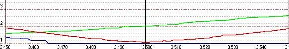
Figure 1 shows the calculated SWR graphs (in APAK-EL) using a quarter-wave cable transformer 13.7m long (with polyethylene dielectric, Ku=0.66) for a dipole with independent resonances of 1.83 MHz and 3.65 MHz, having Rin 50 and 100 Ω, respectively.
It can be seen that the resonance at 80m remained unchanged, but at 160m it shifted down by 10 kHz and the SWR slightly increased. It was on this observation that it was decided to find a compromise length of the transformer for both ranges without regard to the resonant frequency (it can be corrected by changing the geometric length of the antenna).
In Fig.2. shows the SWR graph using the optimal transformer 10.4m long for the same dipole.

The difference in SWR, of course, is small, but it shows that it is possible to select the line in such a way that a compromise is achievable in other, more severe cases.
But I didn’t “catch fleas” at 160m and, due to the broadband, the 80m range, I gave priority in its favor and used exactly a quarter-wave segment of the SAT-50 cable (polyethylene foam, Ku = 0.82) 17.08m long. Here are the resulting graphs of Rin and SWR dipoles (red line - SWR, green - Rin active, blue - Rin reactive):


Doesn't it remind you of the calculated schedule shown in Fig. 1?
Thus, with a sufficiently high accuracy, it was possible to model cable transformers in APAK-EL after receiving the source file of the *.nwl format from MMANA (taking into account, of course, the height of the antenna above the ground in lambdas - a general remark when modeling low antennas in MMANA), not bothering to take accurate data from a real antenna.
With a 160/80 vertical, there were no problems with matching during modeling and it was necessary to think over the issue of switching the entire system: it is necessary to turn on the cable transformer when connecting the dipole, and turn it off when connecting the vertical. As a result, the transformer was wound into a single-layer coil (tnx RZ9CX) and connected by connectors to the switch at the power point, at the same time being a shut-off choke for the dipole.
The resulting graphs for verticals:

All 4 groups of REN-33 relay contacts are used for switching. The influence of the contacts was assumed to be insignificant at these frequencies. The switching of the relay is made according to the "vole" P-274, which is also the carrier cable for the HF power feeder.
Near the power point, 100 M2000NN K20x12x6 rings are put on the feeder RK-50-7, at a distance of 30m 40 more of the same rings are all in a heat-shrinkable tube. In total, the cable route is 50m to the switch and another +55m of the main cable to the shek.
Antenna design
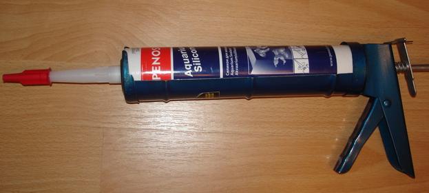
Based on the distance in the span between the houses, which needed to be covered (120m), it was decided to make the entire horizontal part from 3mm bimetal. However, at the very last moment I changed my mind (an indecently heavy construction turns out) and made it from a retinue of a vole. At the ends of the beams, 3 nut insulators 40x28mm with a progressive distance of 40-50cm from each other. The vertical canvas is made of the same cable, but in one thread. Moreover, its length even made it possible not to use a capacitive load - it all fit in height (about 1m did not reach the ground). But this is based on electrical engineering considerations, and from the considerations of residents, of course, it was necessary to raise the lower point of the antenna from the ground, and compensate for the missing length with a capacitive load in the form of two conductors diverging parallel to the ground. In reality, it turned out not quite parallel, but in the form of IV with a peak 5-6m from the ground and an angle at it of about 140 degrees. The power cable is connected perpendicular to all elements of the antenna from the side (from the roof). All open connections are sealed with silicone sealant for aquarium work in a professional tube (for a gun).
traps calculated in TrapRus, I measured the linear capacity of the existing cable myself with a digital meter (I did not take it from the existing database) - I used these data in the calculation. The resulting difference (10pF) with reference data clearly indicated that it is recommended not to use reference data when manufacturing traps, since even cables of the same brand, but from different manufacturers, have different parameters. About 10 years ago I used the CoaxTrap program, but both options sin with one thing: the calculation is carried out for a design that is different from that described in the help file for CoaxTrap, which was described: the obtained capacitance data must be divided by 4, and the inductance value must be multiplied by 4 and use these data in modeling in MMAN. In the rest, everything is accurate, if the linear capacity and the required geometric dimensions are correctly entered, then no adjustment is required.

Connection diagram:
The used cable RK-50-4 is wound on sewer pipe for outdoor installation (red - cost 160-280r per p / meter, depending on the store), the parameters were checked with the AA-330 analyzer, no adjustment was required.
Traps appearance:

A comparison in the direction of Europe with the existing Inverted "V" with a feed point 10m higher (telescope on the roof) showed the following (remember: the dipole hangs sideways to Europe and must lose at least 2 points to the same dipole, but in the perpendicular direction):
- From the switch on the roof to the power point of the existing IV, 35m of the 8D-FB cable was laid, and 50m of the PK-50-7 cable to the new antenna under study.
- In the CW section (where IV was tuned) of both bands towards Europe, no difference was noticed, but the dipole turned out to be less noisy.
- In the SSB section, the difference in reception was up to 20 (TWENTY!) dB, and in transmission from 1 to 2.5 points in favor of the dipole before IV (especially before the vertical).
- Vertical lost up to 3 points.
- Operators from the south (UK, UN) were also in solidarity and leaned towards the dipole, describing its work as "very strong", in turn, below +10dB, none of them were received on my S-meter. However, in the same direction at a distance of 600 km, the vertical outscored the dipole by more than 1 point when communicating with one correspondent who also had a vertical 18 m long spike with capacitive loads. I did not notice a difference in the strength of the received signal of this correspondent between both antennas. It made no sense to compare with IV further - it did not outperform the dipole in all cases, even in the existing configuration ...
- In the direction to the South, at a distance of 10 thousand km. (ZS6) gave preference to the reception of the dipole, as less noisy. In addition, the vertical is narrow-banded and tuned in CW, and since the comparison was at 3793 kHz, it turned out that in the SSB section of his SWR was already indecently high. It was not possible to shout to the correspondent at 100 watts, so it was not possible to compare the antennas for transmission, which is a pity - a very demonstrative experiment would have turned out ...
- So, with the exception of one case, the vertical lost to both antennas (Dipole and IV - studied up to 3000 km), and especially on short distances and already at a distance of 300 km, the difference was indecently large (about 5-6 points of loss of the vertical in front of the dipole). I suppose that if all the correspondents with whom the comparison was made had vertical antennas, the results would be opposite.
- The influence of the dipole on IV due to their relatively close relative position was assessed according to the analyzer readings - graph IV in terms of the reactive component Rin was noticeably smeared, but no real changes and pathologies were noted in its work. The device did not show the reverse effect, as well as the difference in the operation of the dipole after folding IV.
- In the event that the indistinct operation of the vertical surrounded by houses is clarified, in a year I will change the entire system to an asymmetric wave dipole at 80m (just the direction required) and a half-wave dipole at 160m - that's just the issue of coordination will need to be thought through.
Positive side effect: the vertical is an excellent survey antenna for listening to the HF bands in parallel with a directional antenna - in the direction of its rear lobe, it clearly wins and allows you to quickly control the situation "behind" the main radiation of directional antennas.
P.S. The antenna hung for 1 year and was replaced with a . Dismantling showed damage to the insulation of the vole in the places of its attachment to the insulators. Long span for long term installation. Well, it is impossible not to note the weighting agent in the center in the form of a power supply unit with a power cable, a transformer in a box + a drawn vertical.