How to connect a triple switch. Three-key switch with socket: selection and connection How to connect a three-key switch
A switch is the main device designed to control lighting in an apartment. A few years ago, a triple switch was a rarity in homes, but now it is very popular among the population. There is a huge range of such devices, differing in design and modification. The practicality of its use lies in the ability to control three light sources from one control point. If there is a need for such devices, then you need to know how to properly connect a triple switch.
Areas of use
Interior designers are increasingly suggesting dividing light into groups. Multi-level ceilings, arches, niches require separate lighting. Modern studio apartments, divided into zones, provide slightly dim lighting in the recreation area, bright lighting in the functional area near the computer, bookshelf, and armchairs. In the living area, where there is a TV, sofa and dining table, you can use combined light.
How to connect a triple light switch so that it is convenient to use? It will be appropriate:
- in the corridor to connect three rooms to lighting at once - a bathroom, a toilet and a kitchen, if they are located close to each other;
- if the room has a multi-arm chandelier or combined lighting (main and additional);
- when the ceiling is made at several levels;
- if it consists of three parts;
- if you need to control the lighting of three rooms from one point.
Advantages of use
Why is it beneficial to install a triple switch? How to connect it to get benefits?
- Ergonomics - one device looks more beautiful instead of three.
- Cost-effective cable laying - less financial and labor costs will be required.
- The need for one hole in the wall, instead of three.
- Economical in energy consumption, since full illumination with all light bulbs is not always required; sometimes you can get by with some of them.
Types of triple switches
Before installing the switch, you need to decide what function is required from it, based on this, choose the type:
- Ordinary.
- With a light indicator - serve as a beacon for finding a switch or signaling in which rooms the lights are on.

- With a socket - usually used in the corridor near the sanitary rooms.
- Hidden design - for placing the working part inside the wall.
- External version - for placing the housing on the wall.
Criterias of choice
With all the variety of switches on the market, it is recommended to adhere to certain points:
- Models with A modern, convenient way to secure wires in the device.
- No external damage - scratches, cracks, chips.
- Reliable terminals that can firmly fix the wires.
- Clear key operation with a characteristic click, without jamming.
- There is a diagram on the back of the device showing how to connect a triple switch.

Switch device
The operating principle of a triple switch is no different from a double and single switch. Pressing the key to the "On" position closes the contact of the lighting circuit, voltage appears on the lighting device, and the light bulb lights up. Switching the key to the "Off" position opens the contact and the light goes out. Do this on each of the three keys. The switch consists of:
- protective part - keys and frames;
- working part - mechanism for fixing wires and housing.
Switch connection
According to electrical safety precautions, before working with wires, it is necessary to turn off the voltage by turning off the power supply. Before doing this, identify the wires with phase and neutral using a voltage indicator.
If there is a hidden switch, then first of all you need to drill a technical hole for the socket box using a drill with a special conical attachment. A socket box is inserted into this opening, for a more durable installation of which an alabaster solution is used.
A four-core copper cable with a core cross-section of 1.5 mm 2 is supplied to this hole. It is recommended to process the ends of the wires. First, remove the insulation with a sharp knife or stripper. Then put lugs on them that correspond to the terminals on the electrical device, and crimp them with a special hand tool - a crimper. If you don’t have a crimper at hand, you can get by with a soldering iron, twisting the core fibers with your fingers and tinning them. The simplest option is to simply insert the stripped ends of the wires into the clamping devices of the triple switch.
How to connect? The first core is connected to phase B on one side and to the common contact in the switch on the other end. The other three wires go to the three switch terminals located opposite the common contact at one end, and each wire goes to the phase terminal of its lighting fixture (one of the three) at the other end of the cable. This can be seen in the triple switch wiring diagram. You can see how to connect here.

Three coming from the lighting fixtures are connected to each other and to the zero coming from the power supply.
There should be eight wires in the distribution box - three of them come from the power supply (phase, neutral and ground). Zero and grounding go further to the lighting fixtures, and the three phase wires connected to the three chandeliers are also connected to three wires coming from the triple switch. How to connect is indicated in detail in the diagram.
In old wiring, the neutral wires were often twisted directly in the switch socket, behind the operating device, and not in the junction box. Some electricians still practice this method in order to do without additional nodes in the circuit. Thus, there is no need to install a box, which is important for preserving the appearance of the room, especially with expensive wall decoration.
An important rule is that the switch must always open a phase.
Connecting a switch with a socket

How to connect a triple switch with a socket? The diagram is shown below.

It is distinguished by the presence of another neutral wire, coming directly from the power supply and connected directly to the outlet. This device is used in the corridor, next to the plumbing rooms, where an outlet is needed, but making another technical hole separately for the connector is impractical. It is also used when an outlet is rarely needed, because the switch is usually mounted high from the floor level, and the electrical connector is just above the baseboard. How to connect a triple switch with a socket so that it is convenient to use both the connector and the keys? You can choose the optimal height for comfortable operation of the device individually.
Undoubtedly, it is very convenient for controlling light in an apartment. It is necessary to follow the electrical safety rules when installing it, that is, before work, turn off the power supply and check the absence of voltage with an indicator. After work, check the connection according to the diagram again and only then apply voltage to the network.
Man's desire to make living conditions comfortable leads to the emergence of new types of devices and mechanisms. One of them is a triple switch with a socket, which allows you to minimize the space occupied on the wall and make the life of the owner of an apartment (private house) more convenient.
In addition, this approach has several other advantages:
- aesthetic appearance - there is only one control panel of keys with a socket on the wall;
- saving time on laying cables during initial planning or repairs;
- reduction in labor costs due to the installation of one niche for a switch socket instead of several.
Using a block of triple pass-through switch, combined with a socket in one housing, will be appropriate for complex layouts - when several small rooms are located nearby. For example, hallway, bathroom, toilet, kitchen, etc.
Installation of a triple switch in a niche in the wall is done using special supports or spacer tabs on the sides of the device. After the device is securely fixed on top, it is closed with a decorative frame, which can be attached in various ways, but most often with small latches.
Set of tools and algorithm of work
To carry out repairs or install a new block of a triple pass-through switch combined with a socket, you will need:
- a flat or Phillips screwdriver - depending on the type of fastening screw heads;
- stripper - a tool that removes insulation from wiring;
- pliers, wire cutters;
- knife, electrical tape.
The work algorithm as a whole includes the following points:
- disassemble the switch so that you can later install it in a niche in the wall;
- turn off the power supply to the repair or installation site;
- determine the purpose of each of the existing terminals of the electrical appliance;
- establish the connection points of all wires;
- proceed directly to connecting the triple switch.
In order for the device to work correctly and without failures for a long time, perform all actions carefully, taking into account the connection diagram.

Having studied what was written above, you already know approximately how to connect a triple switch in the same housing with a socket. For each such device you will need four single-core wires or a four-core cable. Sometimes you will see that there are two wires: a single wire "phase" and a three wire running through the junction box to the lights.
First, assemble the wires according to the connection diagram using self-clamping terminal blocks or using manual “twisting”. In this case, connect the zero from the output cable together with all the same wires from the lighting fixtures.
Secure the phase from the power cable to the common contact of the switch. You can determine where each wire is in the junction box visually or using special devices: a tester or an indicator screwdriver.
After these steps, there will remain three single-core wires from the switch mechanism and one phase from each of the incandescent light bulbs.
Please note: the connection diagram for such devices indicates that it is the phase cable from the mains that must be connected to the input terminal of the switch, and not the neutral cable. If even one mistake is made during installation, the safe operation of the triple switch is not guaranteed in this case.
In addition, there is a real risk of electric shock even when changing an incandescent light bulb, because all electrical wiring is constantly energized. That is, a minimal breakdown of the insulating layer in the absence of grounding of lighting lamps (luminaires) can lead to unpredictable consequences.
After installing a block of a triple pass-through switch combined with a socket, check its functionality. Turn on all the keys in turn - the lights should light up and turn off.
How to connect wires directly to a switch
The process may be slightly different depending on the model of the triple switch, but in general all actions are performed in the same way.

So, pull out the keys, remove the decorative frame and find the connection terminals. But remember that when performing these and all further work, you need to be extremely careful and attentive to prevent damage to the new electrical appliance.
The cables in the switch mechanism are held in place thanks to clamping screws, which you need to slightly unscrew before starting installation - for unhindered passage of the wires.
Please note that the triple switch connection diagram provides four cable terminals: three output and one input.
First you should determine the location of the common terminal where the phase will be supplied, and then you will see the terminals for each lighting section. As a rule, they are located to the side, on a separate block, or even placed on the back of the electrical appliance.
On each of the wires, you will need to remove no more than 7-10 mm of the insulating layer to prevent bare wires from touching the internal mechanism of the device.
Tighten the clamping screws tightly because there is no play allowed. And use special NShVI lugs if you use multi-core cables. This significantly reduces the risk of wire breaking while tightening it with screw clamps.

After completing all the steps, assemble the outer decorative frame of the triple switch in the reverse order.
The most important thing when installing any such device is to remember safety precautions when working with electrical appliances. Make sure there is no power before you begin disassembling the old switch.
Modern trends in lighting control systems are developing not only in the direction of comfortable operation and varied design, but also increasing the level of efficiency. One such method is to use three-way switches that can control three groups of lighting fixtures from one access point.
The advantages of using a single three-circuit device are obvious. This is an aesthetic appearance, less labor-intensive laying of electrical cables to the connection point. Knocking out one technological niche in the wall to accommodate an installation box instead of several.
Such devices are used to illuminate rooms with complex configurations, long corridors, or control several rooms from one point: a bathroom, a bathroom and a hallway.
Lately, I have often been asked by mail and in the comments and asked for advice on such a seemingly ordinary device. Therefore, today we will examine in detail the topic of how to connect a three-key switch. P.S. in this example it is used three-gang switch schneider electric.
The three-key switch is subjected to more intensive use than other electrical switching equipment. The reliability of the device design should ensure an average service life of up to 10 years. Malfunctions that arise during operation can be divided into two categories:
- - mechanical – associated with the breakdown of the external and internal elements of the case, springs, fasteners, erasing keys, etc.;
- - electrical – loosening of the contact clamps in the electrical part of the mechanism, and, as a result, burning of the cables and the entire device as a whole.
Any breakdowns that lead to a violation of the integrity of the device or its individual elements require replacement of the entire product.
Repair or replacement of switches, like any other electrical equipment, must be carried out by a specialist with the appropriate level of clearance. The room where repair work is carried out must be de-energized.
You can purchase such switches at any electrical goods store. , quite complicated at first glance, will also not present any particular problems after carefully reading the provided article.
Three-gang switch design
A large number of electrical equipment companies produce many models of switches. The devices have significant differences in external design and slightly smaller internal composition. However, the restrictions imposed by a standardized electrical wiring network in apartments force the use of switches with a limited number of switching sections in the control mechanism.
If it becomes possible to carry out a deep modernization of the electrical network, the use of triple switches will provide more flexible and economical control of lighting sources.
Connecting a three-key switch, in fact, is no different from connecting one or two keys.
One of the power cables is connected to the input of the switch, and the lighting cables are connected to the output contacts (to the corresponding contacts of the switching block).
The differences are in the number of contacts of the switching groups - one, two or three. The photograph shows the installation part of a simple, typical three-key switch.
The difference between the input contacts to which the phase is supplied and the output contacts to which the cables leading to the lighting lamps are connected is clearly visible. The neutral wires of each lamp are combined together and connected to the neutral wire in the box.
Installation of the three-key switch mechanism itself into the socket box is carried out using a support which is secured with screws or using special spacer tabs. After the switch mechanism is securely fixed, a decorative frame is installed on top, which is secured with latches.
Three-key switch connection diagram
The use of a triple switch is justified when there is a need to control a large number of lighting zones and/or multi-level lighting. This will make it possible not only to control energy consumption, but also to facilitate the technical implementation of design solutions in the room.

Where are they used?
Modern renovations and design solutions increasingly suggest dividing lighting into different groups.
For example, a room has a complex configuration - niches, ledges, separation by partitions or curtains. Very often now large one-room apartments are divided into zones and made into so-called studios. In this case, a switch with three keys is ideal. By using specially designed and mounted zone lighting, you can highlight a work area where there will be a computer desk, a sofa, shelves with books, here the lighting is made brighter. The second zone is the sleeping area, where more subdued light is quite suitable. The third zone is the living room, where there is a coffee table, armchairs, and a TV; here the lighting can be combined.
When else is it advisable to use a three-key household switch?
- If from one point it is necessary to control the lighting of three rooms at once, for example, a corridor, a bathroom and a bathroom, when they are located close to each other.
- In the case of combined lighting in the room - central and spot.
- When in a large room, lighting is provided by a multi-arm chandelier.
- If the room has a multi-level ceiling made of plasterboard sheets.
- When the lighting of a long corridor is divided into three zones.
Advantages
From installing such a triple switch you will receive the following advantages:
- Externally, one switch with three keys looks more compact and more aesthetically pleasing than three single ones.
- Laying electrical wires to the connection point will be less expensive in terms of labor and money.
- You will need to make one technological niche in the wall for the mounting box instead of three.
- Economic effect. For example, if your chandelier has 3-4 light bulbs, then turning on a single-key switch ensures that all of them work at once, while consuming maximum electricity. But such illumination is not always necessary; dim light is sufficient. If you install a 3-key household switch for such a chandelier, then, if necessary, one or two lamps are turned on, thereby saving almost half of the electricity.
Kinds
Do not rush to connect a three-key switch until you decide exactly what kind of device you want to see in your apartment. After all, these switching devices come in several types:
- Regular.
- Walkthroughs. They are used in long corridors or on different floors, when at the entrance (at the beginning of the corridor or on the first floor) the lighting is turned on by one switch, and when leaving (at the end of the corridor or on the second floor) another switch is turned off. That is, you don’t need to make your way in the dark and crawl along the wall with your hand to find the button of the switching device.
- With indication. Such light beacons have two options for indicating the status of the device. Or they glow when the lights are off and thereby indicate in a dark room where the switching device is located. Or, on the contrary, the beacons light up when the keys are turned on, thereby making it clear where exactly the light is currently turned on.
- Three-key switch with socket. They are most often used in rooms where a toilet, bathroom and corridor are located nearby.
How to choose?
Nowadays there is such a huge range of switches on the electrical goods market that you can find a suitable model and color for any design solution or interior. However, you understand perfectly well that shade and appearance are far from the main indicators that you should pay attention to when choosing a device. When purchasing a three-key switch, check the following:
- The presence of modern self-clamping terminals, they are more convenient to use. Simply insert the wire into the hole and it will immediately be fixed.
- The outer side of the product is without burrs, scratches or damage.
- Normal operation of all terminals; they must ensure reliable fixation of the wire cores.
- The keys do not stick when pressed (on or off) and work clearly, with a clearly audible characteristic click.
- On the reverse side there should be a connection diagram for the triple switch.
Try to avoid cheap Chinese electrical wiring products. Buy devices from trusted companies and manufacturers.
Design

There are no special differences in the design of these switches. The principle of operation is the same as for two- or one-key ones.
Let's consider the main elements of the switching device.
Keys and frame, so-called protective elements. For their manufacture, special heat-resistant plastic is used. The keys directly turn the switch on and off.
The operating mechanism, or actuator, that operates the keys. The frame is connected to the working mechanism with special latches or screws. This entire assembled structure is mounted in an installation box and fixed in it with special spacers.
The connected three-key device must have four contacts - one to connect the power supply wire, three more will connect the switch to the lighting elements. The material for contacts is usually copper; the size varies depending on the cross-section of the wire and the connected load.
The use of this type of switches is more intensive than others, so their average service life is from 8 to 10 years. There can be two main reasons why a device may fail:
- Mechanical - fastening elements were damaged, the housing collapsed.
- Electrical - damage to contacts.
If there is a breakdown, do not try to replace any components in a three-key switch; the device should be replaced completely. It would be better if this is done by a professional electrician in compliance with all safety rules. Although, if you are well acquainted with electrical engineering, have skills in working with power tools, and understand what “phase” and “zero” are, it will not be difficult for you to do this yourself.
Installation and connection
Let's talk a little about how to properly install the device in question. But first of all, about the tools. You must have:
- flat and Phillips screwdrivers;
- a stripper so that you can remove the insulation, or a knife;
- pliers;
- electrical tape or clamps.

A two-wire wire (phase and neutral) comes from the power supply to the distribution box, which is installed in the room.
There should be four wires going to the switch. One is a phase from the power supply (it comes from the distribution box) and three phase wires from lighting fixtures.
The three-key device has 4 contact units:
- input contact, the supply phase must be connected to it;
- three more contacts; the phase conductors of the wires going to the lighting devices are connected to them.
The neutral conductors of the wires going to the lamps must be connected in the distribution box to the neutral wire of the supply network.
When you connect a phase to the input contact of the switch, do not confuse it with the neutral wire. The switching device must break exactly the phase, and not the zero. Otherwise, when replacing lamps in luminaires, you risk getting energized.
Now some practical steps:
- Before connecting the triple switch, ensure that the power is completely disconnected. Turn off the input machine that is installed at the entrance to the apartment. This is an important condition for any work related to electricity.
- There is a connection diagram on the back of the switch. According to it, connect the phase wires from the power supply network and from the lighting fixtures. The contacts are made with self-clamping terminals, so all you have to do is fix the wires in them.
- After this, the switch is secured in the installation box using clamping screws. All that remains is to secure the keys and frame on top.
- Connections in the junction box can be made by twisting. The wire coming from the switch to the lamp is connected to the phase wire of this lighting device. A small part of the wires is stripped, twisted together with pliers, after which the contact is insulated using a special tape. Everything can be simplified if you use modern clamps. Do the same with the remaining two pairs of wires. And in exactly the same way they connect the neutral wires of three lighting fixtures to the network neutral.
- It remains to check the connected switch. Turn on the input machine for the apartment and alternately pressing the keys of the mounted switching device, check whether the lamps of the lamps light up.
A device with which you can control three independent lamps is undoubtedly a very successful and profitable invention of mankind. But still, before you connect the switch, evaluate your knowledge and strength. There are times when it is better to trust the professionals.
Prices for housing and communal services increase every year, which makes us think about saving, including electricity. Moreover, this applies to places that people had never even thought about before. For example, lighting of stairs and landings in multi-storey buildings. In the recent past, when electricity prices were meager, staircases were illuminated 24 hours a day. This problem is also relevant in private houses that have more than one floor connected by a staircase. To save money, you have to turn off the lights, but to do this you need to either go down the stairs again or go up them. This is extremely inconvenient, so sometimes they simply don’t turn it off and it burns until the morning, when it doesn’t get light.
For the convenience of lighting in such areas, so-called “pass-through” switches were developed. They are also called “duplicate” or “change-over”. They can be distinguished from classic switches by the presence of a larger number of contacts. Therefore, in order to connect them, you need to know the circuit, and even more so, be able to understand the principle of their operation. Naturally, this is not entirely simple, but it is absolutely possible.
On the key of the pass-through switch there are two arrows (not large), directed up and down.
 This type is a pass-through single-key switch. There may be double arrows on the key.
 The connection diagram is not much more complicated than the connection diagram for a classic switch. The only difference is in the larger number of contacts: a regular switch has two contacts, and a pass-through switch has three contacts. Two out of three contacts are considered common. In the lighting switching circuit, two or more similar switches are used.
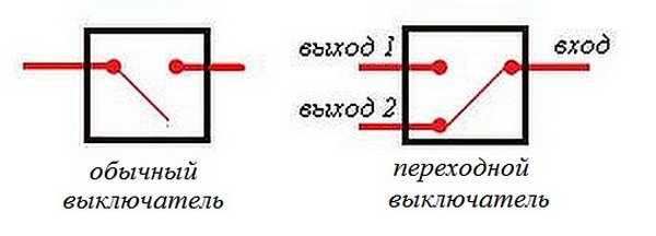 The differences are in the number of contacts
 The switch works as follows: when switching with a key, the input is connected to one of the outputs. In other words, the pass-through switch is designed for two operating states:
- The input is connected to output 1;
- The input is connected to output 2.
It has no intermediate positions, therefore, the circuit works as needed. Since the contacts are simply connected, in the opinion of many experts they should have been called “switches”. Therefore, a transition switch can be safely classified as such a device.
In order not to be mistaken about what kind of switch it is, you should familiarize yourself with the connection diagram, which is present on the switch body. Basically, the circuit is available on branded products, but you won’t see it on inexpensive, primitive models. As a rule, the circuit can be found on switches from Lezard, Legrand, Viko, etc. As for cheap Chinese switches, basically there is no such circuit, so you have to connect the ends with a device.

As mentioned above, in the absence of a diagram, it is better to call the contacts at different positions of the key. This is also necessary in order not to confuse the ends, since irresponsible manufacturers often confuse the terminals during the production process, which means that it will not work correctly.
To ring contacts, you must have either a digital or pointer device. The digital device should be switched to dialing mode. In this mode, short-circuited sections of electrical wiring or other radio components are determined. When the ends of the probes are closed, the device emits a sound signal, which is very convenient, since there is no need to look at the device display. If you have a pointer device, then when the ends of the probes are closed, the arrow deflects to the right all the way.
In this case, it is important to find a common wire. For those who have the skills to work with the device, there will be no special problems, but for those who have picked up the device for the first time, the task may not be solvable, despite the fact that they only need to figure out three contacts. In this case, it is better to first watch the video, which clearly explains and, most importantly, shows how to do it.
Connection diagram for two pass-through switches
Such a scheme can provide significant assistance in organizing lighting on the stairs (in a two-story house), in a long corridor or in a passage room. It can be quite convenient to organize lighting in the bedroom when one switch is installed at the entrance to the bedroom, and the other next to the bed. In this case, you won’t have to constantly get out of bed to turn off the main light.
 Electrical diagram for connecting two pass-through switches
 The connection diagram is very simple and clear: a phase is supplied to the input of one of the switches, the input of the other switch is connected to one of the wires of the chandelier (lamp). The second end of the lamp is connected directly to the neutral wire. The N1 outputs of both switches are connected together, as are the N2 outputs.
The scheme operates quite simply. If you look at the diagram, in this position the light source is turned on. When you subsequently switch any of the switches, in any order, the lamp will turn off and on.
To make it more clear, you should carefully look at the figure.
 Wiring between two pass-through switches.
 If such switches are installed indoors, the wiring should be done as shown in the figure below. Modern requirements allow wiring at a distance of 15 cm from the ceiling. As a rule, wires are laid in special trays or boxes, and the ends of the wires are concentrated in installation (distribution) boxes. This approach has undeniable advantages. The main thing is that a damaged wire can always be replaced. The connection of wires in installation boxes is carried out using special clamps (contact blocks). At the same time, twists are also allowed, which are then necessarily soldered and reliably insulated.
The output of the second switch is connected to one of the conductors going to the lighting lamp. The white conductors are the wires connecting the outputs of both switches.
 Wiring in residential premises
 You can find out how the ends of the wires in the junction box are connected by watching the corresponding video.
Three-point lighting control option
If there is a need for remote control of the lamp from three places, then you will also have to purchase a cross switch. It switches not one, but two contacts at a time, so it has two inputs and two outputs.
How to connect all three switches can be seen in the figure. This is somewhat more complicated than the previous case, but you can understand the principle of operation.
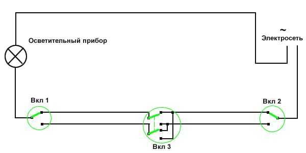 Electrical diagram for switching on a lamp from three places.
 To connect an electric light source, according to this diagram, you must perform the following operations:
- The neutral wire is connected to one of the lamp wires.
- The phase wire is connected to the input contact of one of the pass-through switches.
- The free wire of the lamp is connected to the input contact of the second switch (pass-through).
- The two output contacts of the pass-through switch are connected to the two input contacts of the crossover switch.
- The two output contacts of the second pass-through switch are connected to the two output contacts of the crossover switch.
The diagram is the same, but it is shown more clearly where exactly to connect the wires.
 Which terminals are the wires connected to?
 This is approximately how you should route the wires around the room.

Based on a circuit for three control points, you can assemble circuits for 4 or 5 points. In such cases, it is necessary to increase the number of crossover switches. They should always be installed between two pass-through switches.
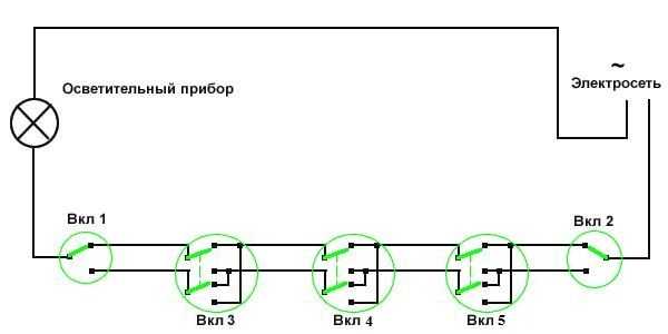 Scheme of organizing on/off lamp for 5 points.
 If you remove one of the cross switches from this circuit, you get a 4-point option, and if you add one cross switch to it, you get a 6-point option.
Two-key pass-through switch: connection diagram
In order to control the operation of two lamps from several points, there are two-key pass-through switches. They have six contacts. The main thing is to identify common contacts. They are determined according to the same principle as when searching for a common contact in single-key pass-through switches.
In a circuit that uses two two-key pass-through switches, significantly more wires are used.
The phase wire is supplied to the inputs of both switches, and the other inputs of the switches are connected to one of the ends of one and the other lamp. The free ends of the lamp are connected to the neutral conductor. The two outputs of one switch are connected to the two outputs of the second switch, and the other two outputs of that switch are connected to the other two outputs of the first switch.
Switches are the main devices for controlling lighting. The most common is single, but if you need to control several lamps from one place, two- and three-key ones are used. The photo below shows a three-gang switch with a socket.
Three-gang switch with socket on the wall
Purpose
A triple or three-key switch is designed to switch three groups of lamps. This can be a combined method of lighting, where spotlights are combined with central lighting, groups of lamps in multi-arm chandeliers, at different levels of a plasterboard ceiling, turning on lights in the bathroom, corridor, toilet. Its advantages are as follows:
- saving electricity;
- compactness;
- beautiful appearance;
- control from one place several light sources in different rooms (bathroom, toilet, kitchen);
- the ability to regulate illumination by switching light sources where it is not possible to use dimmers;
- changing the lighting in the room if necessary.
Options for using multi-key switches:
- changing the lighting intensity of the chandelier;
- control of several lamps (table, pendant, wall);
- control of several lighting zones in one room (lamp, chandelier, backlight).
They also add a socket. The device in the form of a block becomes more functional.
Device selection
Since the choice is quite large, you can find a model that matches the interior of the room . The devices also differ functionally:
- Regular switches.
- Devices with an indicator that can turn on in the dark to indicate its location or indicate which key is on.
- Pass-through switches. They are installed in different places in long corridors or passages, on stairs, on different floors, etc. Through them you can control one or a group of lamps from different places.
There should be no scratches, burrs, abrasions or other damage on the body of the product. The keys should be easy to switch with characteristic clicks, and the terminals should firmly fix the connected wires. Self-clamping terminals work reliably and are more convenient to use. Just insert the wire into the hole and it will be fixed. It is important to remove it correctly if necessary. For this purpose, the device has special latches that can be pressed out. If you pull the wire out of the hole, the connector may become damaged.
Connection
The connection diagram of the switch depends on its type. On the back of the device there is a diagram of its contacts. How they are connected to the lamps can be seen in the figure.

Three-key switch connection diagram
Power wires are supplied to the distribution box: blue zero (N) and brown phase (L). 3 wires from the light bulbs are connected to zero. The phase goes to the switch, where it is connected to terminal (L). From the switch contacts it spreads to the light bulbs, closing their circuits.
The switch is always inserted into the phase wire, not the neutral wire.
Despite the fact that the connection diagram is simple, the following technology for installing the switch must be observed:
- De-energizing the electrical network by turning off the circuit breaker.
- Dismantling the old switch: removing the buttons, removing the frame, loosening the clamping screws, removing the housing from the socket box, freeing the wires. A mark is made on the phase wire that is disconnected from terminal (L). First, the voltage indicator checks for the presence of a phase on it, since the wires may be mixed up. To do this, voltage is temporarily applied. After touching the bare phase wire, the indicator should light up. Then the power turns off again.
- The new switch is connected according to the diagram shown on its reverse side. It shows the terminals for connecting the phase and the other three wires. The clamping screws are first unscrewed a little to allow free entry of wires.
- The switch is mounted in the socket box. The block is fixed with clamping screws, after which the lining and keys are attached.
- The correct operation of the device is checked by pressing the keys one by one.
In old-style apartments, two-key switches are installed to turn on the lighting in the hallway, toilet, bathroom and kitchen (in different combinations). If there are not enough wires to install a triple block, you will have to lay them additionally.
Separate double and triple switches can be installed for larger bathrooms and kitchens where there may be multiple lighting zones.
If a three-key switch with a socket is installed, its connection diagram differs slightly from the previous one. In Fig. Below are two different designs of a three-key switch (a – BVR3; b – BSU3), where the electrical circuit is the same (c). Power is supplied to the contact terminals (5) of the socket through a separate neutral core and phase, connected using a jumper from the block.

Block diagram of a three-key switch with socket
Position 1 indicates the body, 2 – keys, 3 – screw, 4 – cover, 6 – switch contacts.
Connection features
A switch with several keys and a socket is usually installed in one place - near the doors of the bathroom and toilet. The unit makes it possible to control lighting and connect an electric razor, hair dryer and other appliances used in the bathroom.

Connection diagram of a two-key switch block with a socket to power and loads
There are 5 connections made in the junction box (Fig. above). There is also a green grounding wire introduced here, going only to the socket. A lamp with metal parts also requires protection against electric shock. For this purpose, a screw connection is installed on the metal housing.
With a variety of models of a triple switch with a socket, the connection diagram remains the same (Fig. below). The unit is connected in the same way as single or double models. The power cable is connected everywhere to the input of the device, and the wires go from the contacts of the switch block to the lamps that match the number of its keys.

Schematic diagram of a triple switch with socket
The socket has a separate neutral wire and according to the diagram is not connected to the switch. They only have a common phase. All neutral wires from lamps and sockets are connected in the distribution box to the supply neutral. The phase is supplied to the common input contact of the switch. The contacts for the lighting sections are located on a separate block. From them, voltage is supplied to the light bulbs.
Before connecting, 10 mm of insulation is removed from the ends of the wires. To connect them, it is advisable to use NShVI lugs, which prevent the wire from breaking off when tightened with clamps.
The block is mounted in a wall niche using spacer legs or supports, after which a decorative frame is placed on top of it. The methods of attaching it can be very diverse.
Manufacturers
Many people choose triple switches for aesthetic reasons. If the room is decorated in an antique style, Fede models are suitable here. German Gira products have exquisite designs and are in great demand. Legrand models, horizontal or vertical, adapt well to the interior. ABB provides a large selection of switches. Products are available with LED lighting, adding functionality to the aesthetics.
Combined switches are manufactured by the domestic manufacturer Kuntsevo-Electro. A block made of durable plastic is used for vertical installation in niches on the walls. The following models of triple switches with socket are available:
- BELLA BKVR-039 – with a socket without a grounding contact (Fig. a below);
- BELLA BKVR-212 – with red indicator light (Fig. b);
- BELLA BKVR-036 – with a European socket equipped with protective curtains (Fig. c).

Three-gang switches with socket
The switches have the following characteristics: voltage 220 V, rated load current 10 A. Models with a rated current of 16 A and with a grounding contact are produced by NPO Elektrotekhnika (models BZVRzk-S “REONE”, BZVRzksh-S “REONE”).
Installation of the socket. Video
You can learn in detail about installing sockets and replacing the combined unit BKVR-039 from the video below.
A triple switch with a socket is rarely used, but it is convenient when you need to control several light sources from one point where you need to connect electrical appliances. The unit is multifunctional and takes up little space, since three devices are combined in one.
Connecting a three-key switch is a little more complicated than a one-key switch. The difference is that it has three output contacts to the light bulbs. The block socket works as a separate device, and the neutral wire from the distribution box is connected to it, and the phase is connected through a jumper from the switch.
Did you like the video? Subscribe to our channel!
Today we want to tell you how to connect a three-key switch using the example of lighting in the kitchen, bathroom and toilet.
Before you begin installing a three-key light switch, you need to purchase the following materials:
Power 3- and 4-core cable with a core cross-section of 1.5 mm² (for example, produced by KZ KABEX). If the shield is not connected to protective grounding or the housings of the lamps that will be installed are made of plastic, you will need a 2-core cable without a grounding conductor (for example, produced by KZ KABEX);
. connection box with a diameter of 100 mm;
. mounting box in which the 3-key switch will be installed;
. 3-key switch;
. installation and fastening accessories (clamps, markings, terminals, etc.);
. lamps.
In addition, to mount a three-key switch and lay the cable, you must have the following tools:
Tools for making “grooves” in the wall (wall cutter or grinder with a diamond blade and a hammer drill with a flat blade, as well as crowns for round holes);
. a screwdriver with a set of attachments or a set of screwdrivers;
. screwdriver with indication or tester (multimeter);
. assembly knife and pliers or tool for removing insulation;
When performing electrical installation work, it is important to follow safety regulations. Therefore, before starting work, it is necessary to turn off the voltage: move the circuit breaker lever (AB) to the lower position and check for the presence of voltage. To do this, use the indicator to touch the unconnected terminal of the machine. If the voltage is turned off, the LED located in the screwdriver will not light up. If the indicator lights up, then there is still voltage, and this may indicate a malfunction of the machine. In this case, you must contact a qualified specialist who will replace the protective device.
When using the tester, you must first set the switch to measure alternating voltage (indicated by “~V” or “ACV”) and set 750 V. After this, touch the circuit breaker terminal with one probe, and the neutral bus with the other. If the value “0” on the indicator has not changed, there is no voltage and you can proceed with installation; if the value is above zero, you must contact a qualified specialist who will replace the protective device.
After making sure that power is not supplied, you can move on to the next stage - preparatory construction work. Using a wall chaser or grinder and a hammer drill, first, vertical and horizontal special grooves are made - grooves, and also holes are made for installing junction and mounting boxes. It should be noted that it is recommended to install a three-key light switch at a height of 0.9-1.5 m above the floor level. Also, when choosing the place where the 3-key switch will be installed, it is necessary to take into account the following factor - access to the switch should not be hampered by an open door.
After the preliminary work has been completed, you can begin laying the cable to connect the three-key switch. We lay a 3-core cable from the switchboard to the junction box, leaving a margin of approximately 10-15 cm at the end. It is necessary to leave a margin so that in case of damage, it is possible to reconnect, connect or branch the cable cores.
Connection in the electrical panel
Using a construction knife, pliers or a special tool for stripping the cable, we strip the cable and connect its cores according to the following diagram:
Circuit breaker terminal (phase) - wire of white or natural (gray) color;
. free terminal of the zero bus (working zero) - blue (light blue) wire;
. the free terminal of the grounding bus (grounding) is a yellow-green wire.
In the junction box, the sheath and insulation are also removed. For ease of identification, it is recommended to mark the cable cores with special markers. The best way to mark it is as follows:
Gray or white wire (phase) - marked “L”
. blue wire (working zero) - marked “N”;
. yellow-green wire (grounding) - marked “PE”.
Connection diagram for a three-key switch and its installation
To correctly connect a three-key light switch, you will need a 4-core cable with any core color except yellow-green (for example, produced by KZ "KABEX", manufactured according to GOST 31996, with insulation in white (gray), brown, black and blue) .
From the distribution box to the place where the three-key switch is supposed to be installed, we lay a 4-core cable in the groove in this way: we clean the cable sheath and cores on both sides, and for easy identification of the cores we mark:
White (gray) core - marked “L” (main phase from the switchboard to the circuit breaker);
. brown wire - marked “L1” (phase for the first lamp);
. black core - marked “L2” (phase for the second lamp);
. blue wire - marked “L3” (phase for the third lamp).
.jpg) Before starting work, you need to decide how to connect the three-key switch. To do this, you need to look at the back of the switch. On the back side there is a connection diagram for a three-key switch, from which you can understand which terminal should be connected to which cable. Most often, the connection of a three-key switch is carried out as follows: we connect the white (gray) core marked “L” to the upper terminal of the switch, and the cores marked “L1”, “L1” and “L3”, respectively, to the lower terminals. After connecting the cable cores to the appropriate terminals, the 3-key switch can be secured in the installation box using the switch claws or special screws.
Before starting work, you need to decide how to connect the three-key switch. To do this, you need to look at the back of the switch. On the back side there is a connection diagram for a three-key switch, from which you can understand which terminal should be connected to which cable. Most often, the connection of a three-key switch is carried out as follows: we connect the white (gray) core marked “L” to the upper terminal of the switch, and the cores marked “L1”, “L1” and “L3”, respectively, to the lower terminals. After connecting the cable cores to the appropriate terminals, the 3-key switch can be secured in the installation box using the switch claws or special screws.
Connecting lighting fixtures
To connect lamps that will be controlled via a three-key light switch, you will need a 3-core cable (for example, produced by KZ "KABEX", manufactured according to GOST 31996, with insulation in white (gray), blue and yellow-green colors).
From the distribution box to the place where the first lamp is supposed to be installed, the above cable is laid in a groove, as well as in a pipe installed in the ceiling. To pull the cable through the pipe, it is recommended to use a galvanized cable with a polymer coating. After this, you need to strip the cable on both sides and mark the wires:
The core is white (gray) - marked “L1” (phase of the first lamp);
. blue wire - marked “N” (zero);
. yellow-green wire - marked “PE” (grounding).
After fixing the lamp, you can connect it. If the strands of the lamp wire are multi-wire, then they must first be crimped using lugs. After this you can connect:
.jpg) . blue cable core - lamp wire of the same color (blue or light blue);
. blue cable core - lamp wire of the same color (blue or light blue);
. yellow-green cable core (grounding) - a special bolted connection on the lamp body or yellow-green lamp wire;
. the white (gray) core is the remaining wire. Most often this is a wire with black or brown insulation.
The connection of the remaining lamps is carried out in the same way as the first lamp, with one difference - the white (gray) wires are marked “L2” and “L3” (luminaire phase 2 and 3, respectively).
 After we have completed the installation and connection of the lamps, we return to the distribution box, in which the cores with the same markings must be combined into groups and connected using soldering, welding or terminal connectors (for example, self-clamping or Wago screw terminals).
If you do not have grounding, or the housings of the lighting fixtures are made of plastic or other non-conducting material, then the connection diagram for the three-key switch remains the same. However, to connect cables with a grounding conductor (3-core) it is necessary to replace them with 2-core cables, for example, cable.
After all the work is completed, a frame and keys are installed on the switch mechanism, and lamps and shades are inserted into the luminaires.
The video, which is attached at the beginning of this article, clearly shows the connection of a three-key switch and three lamps.