Scheme of a magnetic antenna 40 meters from a hoop. Magnetic antenna (frame) for HF bands
This post is for beginners.
radio amateurs and for those who do not have access
on the roof of your house. Sushko S.A. (ex. UA9LBG)
Magnetic antennas (Magnetic Loop) type-ML due to their small size are becoming more and more popular. All of them can be placed on balconies and window sills. It is undeniable that single-turn magnetic antennas with a vacuum capacitor and a communication loop have won classical popularity, with the help of which it is possible to conduct radio communications even with other continents.
Two-loop antennas in the form of a figure eight relatively recently began to appear among radio amateurs, although at the dawn of the advent of CBS communications in Russia, such antennas were practiced with some success in car radio security systems in the 27 MHz band, see Fig. 1.a. The car antenna consisted of two identical frames (loops) L1; L2 and a common resonant capacitor C1, standing in the antinode of the voltage. With an antenna perimeter of about 5 meters, radio amateur Sterlikov A. ( RA9SUS) conducted communications with 36 countries with a power of up to 30 watts. The antenna was powered directly from the coaxial cable. And such antennas have been practiced since the late 60s, early 70s of the last century. The equivalent circuit of such an antenna is shown in Fig. 1.b.
Although single-turnMLare currently widely used among radio amateurs, a feature of the two-turn one is that its aperture is twice as large as that of the classical one. Capacitor C1 can change the resonance of the antenna with a frequency overlap of 2-3 times, and the total perimeter of the circle of two loops ≤ 0.5λ. This is commensurate with a half-wave antenna, and its small radiation aperture is compensated by an increased quality factor. Coordination of the feeder with such an antenna is best done through inductive or capacitive coupling.
Theoretical digression: The double loop can be considered as a mixed oscillatory systemLL andLC systems. Here, for normal operation, both arms are loaded on the radiation medium synchronously and in phase. If a positive half-wave is applied to the left shoulder, then exactly the same is applied to the right shoulder. The self-induction EMF that originated in each arm will, according to the Lenz rule, be opposite to the induction EMF, but since the induction EMF of each arm is opposite in direction, the self-induction EMF will always coincide with the direction of the induction of the opposite arm. Then the induction in the coil L1 will be summed up with the self-induction from the coil L2, and the induction of the coil L2 - with the self-induction L1. Just as in the LC circuit, the total radiation power can be several times greater than the input power. Energy can be supplied to any of the inductors and in any way.
Transforming the antenna from a rectangular shape to a round one (Fig. 1.a), we get the antenna shown in Fig. 2.a. It is rightly believed that the round shape of the magnetic antenna is more efficient than the rectangular one.
Gradually, the design of the frame L1 and L2 was simplified, they began to be included in the form of a figure eight, in Figures 2.a. and 2.b. So there was a two-frame ML in the form of an eight. Let's call it conditionally ML-8.
ML-8, unlike ML, has its own peculiarity - it can have two resonances, the oscillatory circuit L1; C1 has its own resonant frequency, and L2; C1 has its own. The task of the designer is to achieve unity of resonances and maximum efficiency of the antenna, therefore, the manufacture of loops L1 and L2 must be the same. In practice, an instrumental error of a few centimeters changes one or another inductance, the resonance tuning frequencies diverge, and the antenna receives a certain frequency delta. Sometimes the designer does this on purpose. This is especially convenient for multi-turn loops. In practice, ML-8s make heavy use of the LZ1AQ; K8NDS and others unequivocally stating that such an antenna works much better than a single-loop one, and changing its position in space can be easily controlled by spatial selection, which is confirmed by the photo below in the text of the antenna at 145 MHz.
Preliminary calculations show that for the ML-8 for a range of 40 meters, the diameter of each loop at maximum efficiency will be slightly less than 3 meters. It is clear that such an antenna can only be installed outdoors. And we dream of an efficient ML-8 antenna for a balcony or even a window sill. Of course, you can reduce the diameter of each loop to 1 meter and adjust the resonance of the antenna with capacitor C1 to the required frequency, but the efficiency of such an antenna will drop by more than 5 times. You can go the other way, keep the calculated inductance of the loop, using not one, but two turns in it, leaving the resonant capacitor with the same rating. Undoubtedly, the antenna aperture will decrease, but the number of turns "N" will partially compensate for this loss, according to the formula below:
From the above formula it can be seen that the number of turns N is one of the multipliers of the numerator and is in the same row, both with the area of the turn-S, and with its quality factor-Q.
For example, a radio amateur OK2ER(see Fig.3) considered it possible to use a 4-turn ML with a diameter of only 0.8m in the range of 160-40m.
The author of the antenna reports that at 160 meters the antenna works nominally and is used more for radio surveillance. In the range of 40m. it is enough to use a jumper that reduces the working number of turns by half. Let's pay attention to the materials used - the copper pipe of the loop is taken from water heating, the clips connecting them into a common monolith are used to install plastic water pipes, and a sealed plastic box was purchased at an electrician's store. The matching of the antenna with the feeder is capacitive, and probably according to one of the presented schemes, see Fig.4.
In addition to the above, we need to understand what negatively affects the quality factor-Q of the antenna as a whole:
From the above formula, we see that the active resistance of the inductance Rk and the capacitance of the oscillatory system Sk should be minimal. That is why all MLs are made from a copper pipe of as large a diameter as possible, but there is a case when the loop fabric is made of aluminum, and the quality factor of such an antenna and its efficiency drops from 1.1 to 1.4 times.
As for the capacitance of the oscillatory system, everything is more complicated here. With a constant loop size L, for example, at a resonant frequency of 14 MHz, the capacitance C will be only 28 pF, and the efficiency = 79%. At a frequency of 7 MHz, efficiency = 25%. Whereas at a frequency of 3.5 MHz with a capacitance of 610 pF, its efficiency = 3%. Therefore, ML is most often used for two ranges, and the third (lowest) is considered simply an overview. Consequently, in the calculations we will “dance from the stove”, i.e. from the highest range selected by the radio amateur with a minimum capacitance C1.
ML-8 radiation pattern remains exactly the same as the ML variant. Both versions of the antennas completely retain the eight-width radiation pattern and the corresponding polarization. In the photo, using a gas discharge lamp, the radiation levels of the antenna are clearly shown from different sides.
We design an antenna for a range of 20m.
Now armed with some basic knowledge of ML-8 design, let's try to manually calculate our antenna.
The wavelength for a frequency of 14.5 MHz is (300 / 14.5) - 20.68m.
The circumference of each quarter-wave loop L1; L2 will be 5.17m. Let's take -5m.
The frame diameter will be: 5 / 3.14 - 1.6m.
Conclusion: A single ML hinge may fit into a balcony interior, but an ML-8 is unlikely...
Let's fold each loop in half, but its diameter, while maintaining the given inductance (4 μH), will slightly differ in the smaller direction. Let's resort to a fairly popular radio amateur calculator and determine the geometric dimensions of a two-turn loop with the same inductance.
In accordance with the calculations, the parameters of each loop will be as follows: With a web (copper pipe) diameter of 22mm, the diameter of the double loop will be 0.7m, the distance between the turns will be -0.21m, the loop inductance will be 4.01uH. The required design parameters of the loop to other frequencies are summarized in Table 1.
Table 1.
|
Tuning frequency (MHz) |
Capacitor C1 (pF) |
Bandwidth (kHz) |
|
Note: The ML-8 antenna has not only increased bandwidth, but also increased gain.
In height, such an antenna will be only 1.50-1.60 m. Which is quite acceptable for an antenna of the type - ML-8 of a balcony version and even an antenna hung outside the window of a residential high-rise building. And its wiring diagram will look like in Fig. 6.a.
Antenna Power may be capacitive or inductive. Capacitive coupling options are shown in Fig. 4 and can be selected at the request of the radio amateur.
The most budget option is inductive coupling. It is not worth repeating in a schematic representation of the communication loop, it is completely identical to that of ML-type antennas, except for calculating its perimeter.
Calculation of the diameter (d) of the communication loop ML-8 made from the calculated diameter of two loops.
The circumference of two loops is after recalculation 4.4 * 2 = 8.8 meters.
Calculate the imaginary diameter of two loops D = 8.8m / 3.14 = 2.8 meters.
Calculate the diameter of the communication loop-d= D/5. = 2.8/5 = 0.56 meters.
Since in this design we use a two-turn system, the communication loop must also have two loops. We twist it in half and get a two-turn communication loop with a diameter of about 28cm. The selection of communication with the antenna is carried out at the time of clarifying the SWR in the priority frequency range. The communication loop can have a galvanic connection with the zero voltage point (Fig. 6.a.) and be located closer to it.
Antenna tuning and indication elements
1. To resonate a magnetic antenna, it is best to use vacuum capacitors with high breakdown voltage and high Q factor. Moreover, using a gearbox and an electric drive, its adjustment can be carried out remotely.
We are designing a budget balcony antenna, which can be approached at any time, changed its position in space, rebuilt or switched to another frequency. If at points “a” and “b” (see Fig. 6.a.) instead of a scarce and expensive variable capacitor with large gaps, connect a capacitance made of RG-213 cable segments with a linear capacitance of 100pF / m, then you can instantly change the frequency settings, and the tuning capacitor C1 to refine the tuning resonance. The capacitor cable can be rolled up and sealed in any of the ways. Such a set of containers can be available for each range separately, and included in the circuit through a conventional electrical outlet paired with an electrical plug. Approximate C1 capacities by ranges are shown in Table 1.
2. It is better to indicate the tuning of the antenna to resonance directly on the antenna itself (it is clearer this way). To do this, it is enough not far from the communication coil on canvas 1 (zero voltage point) to wind tightly 25-30 turns of MGTF wire, and seal the setting indicator with all its elements from precipitation. The simplest scheme is shown in Fig.7.
Electric emitter, this is another additional element of radiation. If the magnetic antenna emits an electromagnetic wave with the priority of the magnetic field, then the electric emitter will perform the function of an additional emitter of the electric field-E. In fact, it should replace the initial capacitance C1, and the drain current, which previously passed uselessly between the closed plates of C1, now works for additional radiation. Now the share of the input power will be additionally radiated by electric emitters, fig. 6.b. The bandwidth will increase to the limits of the amateur band as in EH antennas. The capacitance of such emitters is low (12-16pF, no more than 20), and therefore their efficiency in low-frequency ranges will be low. You can get acquainted with the work of EH antennas at the links:
Antenna type ML-8 radio observer greatly simplifies the design as a whole. As the material of the loops L1; L2, you can use cheaper materials, for example, a PVC pipe with an aluminum layer inside for laying a water pipe with a diameter of 10-12 mm. Instead of high-voltage capacitors, ordinary ones with a small TKE can be used, and for smooth tuning to the frequency, double varicaps with control from the radio observation site can be used.
Conclusion
All mini-antennas, whatever they may be, in relation to simple stretch and classic antennas, require a lot of labor and plumbing skills. But the inability to install outdoor antennas, radio amateurs are forced to use both EH and ML antennas. The design of the two-turn Magnetic Loop is convenient because all the elements of adjustment, matching and indication can be placed in one hermetic case. The antenna itself can always be hidden from picky neighbors using one of the available methods, a great example is in the photo below.
At the mention of a magnetic antenna, those on a ferrite rod somehow immediately come to mind, and this is partly correct. These are all variations of the same type of device. A loop antenna is called magnetic, the perimeter of which is much smaller than the wavelength. The well-known zigzag and bi-square (almost the same) are also relatives of the technology in question. And they have absolutely nothing to do with antennas on a magnetic base. It's just a mounting method, nothing more. The magnetic base for the antenna securely holds it on the roof of any car. We are talking today about a special design. The whole beauty of magnetic antennas is that it is possible to provide a relatively large gain at relatively long wavelengths. In this case, the size of the magnetic antenna is quite small. Let's discuss our title and tell you how a do-it-yourself magnetic antenna can be made.
Magnetic Antennas
It is known from theory that almost no radiation occurs in an oscillatory circuit of an inductor and a capacitor. It is all closed, and the wave can swing at the resonant frequency for an arbitrarily long time, fading, due to the presence of active resistance. Yes, the circuit elements, inductance and capacitance, in general, have a purely reactive (imaginary) impedance. Moreover, the size depends on the frequency according to a rather uncomplicated law. This is something like the product of the circular frequency (2 P f) by the value of the inductance or capacitance, respectively. And now, at a certain value, the imaginary components opposite in sign become equal. As a result, the impedance becomes purely active, ideally it is zero.
In reality, the beats are still damped, because in practice each circuit is characterized by a quality factor. Recall that the impedance consists of a purely active (real) part, such as resistors, and an imaginary one. The latter include capacitances whose resistance is imaginary negative and inductances with positive imaginary resistance. Now imagine that in the circuit of the capacitor plates they began to part until they were at opposite ends of the inductance. This is called a vibrator (dipole) Hertz, and is a kind of shortened half-wave and other types of vibrators.
If we take and turn the coil into a single ring, then we get the simplest magnetic antenna. This is a very simplistic interpretation, but that's pretty much how it is. Moreover, the signal is taken from the opposite side of the capacitor through an amplifier on field-effect transistors. This ensures high sensitivity of the device. Well, the antenna on a ferrite rod is a kind of magnetic, only it has many rings instead of one. This type of device got its name for its high sensitivity to the magnetic component of the wave. In particular, when working on a transmission, it is precisely it that is generated, generating a response of the electric field.
The directivity maximum corresponds to the axis of the rod. And both directions are equal. Due to the small perimeter of the loop antenna relative to the wavelength, its resistance is quite low. It can be not just 1 ohm, but even fractions of an ohm. An approximate value can be estimated by the formula:
R = 197 (U / λ) 4 ohm.
U is the perimeter in meters, in the same units as the wavelength λ. Finally, R is the resistance to radiation, do not confuse it with the active one that the tester shows. This parameter is used when calculating the amplifier for load matching. Therefore, for ferrite antennas, this value must be multiplied by the square of the number of turns.
Properties of magnetic antennas
And now let's see how to make a magnetic antenna yourself. First you need to determine the circumference and capacitance of the trimmer capacitor. In fact, the features of a magnetic antenna are such that it requires mandatory coordination, but more on that some other time. The fact is that the hallmark is the incredible number of options for carrying out this operation, so that a separate topic for conversation emerges.

The length of the perimeter of the magnetic antenna ranges from 0.123 to 0.246 λ. If you want to cover this entire range, then you need to choose the right capacitor. In free space and a magnetic antenna, the radiation pattern is in the form of a torus, which can be observed by placing the coil parallel to the ground. The polarization will then be linear horizontal. That is, it is an excellent option for receiving television broadcasts. The disadvantage is that the angle of elevation of the petal depends on the height of the suspension. It is believed that for the distance to the Earth λ it will be 14 degrees. And this impermanence is a negative quality. But for radio, magnetic antennas are used quite often.
The gain is 1.76 dBi, which is 0.39 less than that of the half wave vibrator. But the size of the latter for this frequency will be tens of meters - well, where can you put such a hulk? Draw your own conclusions. Our magnetic antenna is not that big (the perimeter can be 2 meters for a wavelength of 20 meters, which is less than a meter across). For comparison, at a frequency of 34 MHz, which is well known to truckers thanks to walkie-talkies, the wavelength is 8.8 meters. At the same time, everyone knows that not every Kamaz will fit a good half-wave vibrator. And, by the way, earlier we already gave a description of the design of the loop antenna formed by the rubber gasket of the rear window of a VAZ car. For all its small dimensions, the device worked quite well.
By the way, this design is considered more pragmatic than typical whip antennas for cars, where tuning is done by changing the inductance. There are fewer losses. In addition, the radiation pattern covers fairly high elevation angles, almost to the vertical. In the case of a whip antenna, this possibility is not available.
But how to choose the right circumference? With its increase, the gain increases. That is, it must satisfy the condition given above, and be as large as possible. At the same time, do not forget that sometimes you need to block several frequencies. In addition, as the perimeter grows, the bandwidth of the device increases. I must say, with a typical channel width of 10 kHz, this is not so important. In addition, neighboring carriers of broadcast stations will be automatically cut off. In this sense, more does not necessarily mean better. Do not forget, however, that for the sake of amplification, all the fuss was started. Thus, the antenna is selected along the maximum perimeter to ensure the desired selectivity.
Now the main question: how to determine the capacity? So that, together with the inductance of the loop, they form a resonance according to the well-known formula. As for determining the contour parameters, the following formula is given for it:
L = 2U (ln(U/d) - 1.07) nH;
where U and d are the length of the coil and its diameter. What's the catch here? U \u003d P d, therefore, instead of their ratio, one could take the natural logarithm of the number Pi. Whether this is the author's mistake, we do not undertake to say. Perhaps, the fact is taken into account that the tuning capacitor takes away part of the length, as well as the amplifier ... We find the capacitance from the known inductance from the expression for the resonance of the circuit:
f = 1/ 2P √LC; where
C \u003d 1 / 4P 2 L f 2.
Magnetic loop home antenna is a great alternative to classic outdoor ones. Such designs allow you to transmit signals up to 80 m. For their manufacture, coaxial cable is most often used.
The classic version of the magnetic loop antenna
A frame magnetic installation is a subtype of small-sized amateur antennas that can be installed anywhere in a populated area. Under the same conditions, the frames show a more stable result than analogues.
In home practice, the most successful models of popular manufacturers are used. Most of the circuits are given in the amateur literature of radio engineers.

Indoor Magnetic Coaxial Loop Antenna
Do-it-yourself antenna assembly
Materials for manufacturing
The main element is a coaxial cable of several types, 12 m and 4 m long. To build a working model, you also need wooden planks, a 100 pF capacitor and a coaxial connector.
Assembly
A magnetic loop antenna is constructed without special training and knowledge of technical literature. Adhering to the assembly order, you can get a working device the first time:
- connect wooden planks with a cross;
- cut grooves in the boards, corresponding to the radius of the conductor with a depth;
- drill holes on the slats at the base of the cross to secure the cable. Cut three grooves between them.
Accurate dimensional exposure allows you to build a structure with high radio frequency reception.
Form of magnetic frames
A magnetic antenna made of coaxial cable is a loop of conductor that is connected to a capacitor. The loop, as a rule, has the form of a circle. This is due to the fact that this form increases the efficiency of the design. The area of this figure is the largest in comparison with the area of other geometric bodies, therefore, the signal coverage will be increased. Manufacturers of goods for radio amateurs produce exactly round frames.

Installation of the structure on the balcony
In order for the devices to work on a specific wavelength range, loops of various diameters are constructed.
There are also models in the form of triangles, squares and polygons. The use of such structures is determined in each case by various factors: the location of the device in the room, compactness, etc.
Round and square frames are considered single-turn, because. the conductor is not twisted. To date, special programs such as KI6GD allow you to calculate the characteristics of only single-turn antennas. This type has proven itself well for working on high-frequency ranges. Their main disadvantage is their large size. Many specialists tend to work at low frequencies, which is why the magnetic frame installation is so popular.
Conducted comparative calculations of several circuits with one, two or more turns, under similar operating conditions, showed the dubious efficiency of multi-turn structures. The increase in turns is most expedient only to reduce the dimensions of the entire device. In addition, for the implementation of this scheme, it is necessary to increase the consumption of the cable, therefore, the cost of homemade unreasonably increases.
Magnetic frame sheet
For maximum efficiency of the installation, one condition must be achieved: the loss resistance in the frame web must be comparable to the radiation resistance of the entire structure. For copper thin tubes, this condition is easily met. For coaxial cables of large diameter, this effect is more difficult to achieve due to the high resistance of the material. In practice, both types of structures are used, because. other types perform much worse.
receiving frames
If the device performs solely the function of a receiver, then ordinary capacitors with solid dielectrics can be used for its operation. Receiving frames to reduce the size are multi-turn (made of thin wire).
For transmitting devices, such designs are not suitable, because. the action of the transmitter will work to heat the installation.
Coaxial cable braid
The braid of the magnetic frame gives greater efficiency than copper tubes and a thickening of the conductor diameter. For home experiments, models in a black plastic shell are not suitable, because. it contains a large amount of soot. During operation, metal parts with strong heating of the shell emit chemical compounds harmful to humans. In addition, this feature reduces the transmission signal.

Coaxial cable SAT-50M made in Italy
This type of coaxial cable is only suitable for large antennas, as their conductor radiation resistance fully compensates for the input resistance.
Impact of external factors
Due to the physical properties of coaxial cables, the antennas are not affected by temperature and precipitation. Only the shell created by external factors - rain, snow, ice - can be negatively affected. Water has higher losses than cable at high frequencies. As practice shows, it is possible to use such structures on balconies for several decades. Even in severe frosts, there is no significant deterioration in reception.
To increase reception, it is better to place magnetic devices made of coaxial cable in rooms or places of reduced exposure to precipitation: under roof peaks, on protected parts of open balconies. Otherwise, the device will work primarily to heat the environment, and only then to receive and transmit signals.
The main condition for stable operation is the protection of the capacitor from external influences - mechanical, weather, etc. With prolonged exposure to external factors, an arc may form due to high-frequency voltage, which, when overheated, quickly leads to a tap from the circuit or failure of this part.
Frames for high-frequency ranges are horizontal. For low-frequency, with a height of more than 30 m, it is advisable to build vertical structures. For them, the installation height does not affect the reception quality.
Device Location
If this mechanism is located on the roof, then one condition must be provided - this antenna must be higher than all the others. In practice, it is often impossible to achieve ideal placement. The magnetic frame installation is quite unpretentious to the close location of third-party objects and structures - ventilation towers, etc.
The correct location is on the roof with the core in the distance so that there is no absorption of the signal by large models. In view of this, when installed on a balcony, its efficiency decreases. This arrangement is justified in cases where conventional receivers do not work correctly.
Synchronization of frame and cable
Coordination of parts is achieved by placing a small inductive loop in a large one. For symmetrical connection, a special balancing transformer is included in the device. For unbalanced - connect the cable directly. The antenna is grounded at the point where the cable is attached to the base of the large circle. The deformation of the loop helps to achieve a more accurate setting of the device.

Modification of a coaxial cable device
Pros and cons of the device
Advantages
- low cost;
- ease of installation and maintenance;
- availability of raw materials;
- installation in small rooms;
- durability of the device;
- effective work near other radio devices;
- no special requirements to achieve high-quality reception (such devices work stably both in summer and winter).
Flaws
The main disadvantage is the constant adjustment of the capacitors during the change of operating range. The noise level is reduced by turning the structure, which can be extremely difficult during operation due to the geometric shapes and arrangement of wooden planks. Due to radiation at close range, information is transmitted from magnetic tapes (when the tape recorder is turned on) to devices with inductors (TVs, radios, etc.) even when the antennas are turned off. The level of interference can be reduced by changing the location of the device.
During operation, do not touch the metal parts, due to strong heat, you can get burned.
We do it ourselves. Video
How to make a broadband active antenna with your own hands, you can learn from this video.
The magnetic loop antenna is the most cost effective solution for home use. The main advantages are operation at different frequencies, ease of assembly and compactness. A well-made device can receive and transmit an excellent signal over a fairly long distance.
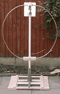
The good results obtained with the "Magnetic Loop" antenna prompted I1ARZ to try building an antenna for the low bands. Initially, he intended to build a circular loop antenna (Fig. 1) with a perimeter of about 10.5 m, which is a quarter of a wavelength on the 7 MHz band. For this purpose, a loop was made of a copper tube with a diameter of 40 mm with thin walls. However, in the course of the work, it turned out that bending and unbending tubes of such sizes is quite difficult, and the shape of the antenna was changed from round to square. Some decrease in efficiency is offset by a significant simplification of manufacturing.
For the range of 1.8 ... 7.2 MHz, you can use a copper tube with a diameter of 25 ... 40 mm. You can also use duralumin tubes, but not everyone has the ability to weld in argon. After assembly, the entire antenna frame is covered with several layers of protective varnish.
The tuning capacitor is very important for the proper operation of the antenna. It must be of good quality, with a large gap between the plates. A vacuum capacitor with a capacity of 7 ... 1000 pF with an allowable voltage of 7 kV is used. It can withstand more than 100 W of power in the antenna, which is quite enough. In the case where the 160 m range is used, the capacitance should reach 1600 pF.
The square-shaped loop is assembled from four copper tubes 2.5 m long and 40 mm in diameter. The tubes are connected together using four copper water pipes. The tubes are welded to the knees. Opposite sides of the frame should be parallel to each other. A piece 100 mm long is cut out in the middle of the upper tube, a Teflon spindle is inserted into the cutout and fixed on both sides with clamps and screws. The diagonal of the loop is 3.4 m, the total length is 10.67 m (together with copper plates 50 mm wide, to which the ends of the tube are attached, providing the connection of a tuning capacitor). To ensure reliable contact, the plates must be welded to the ends of the tube after they are attached.

Figure 2 shows the construction of the frame together with the base and the carrier mast. The mast must be dielectric, for example, made of fiberglass rod. You can also use a plastic tube. In the lower part, the frame is fixed on the carrier mast with steel clamps (Fig. 3).
To strengthen the lower horizontal piece of the frame, a heated copper tube of a slightly larger diameter is pulled over it over a length of approximately 300 mm. The motor that rotates the condenser is mounted on a steel pipe at a height of about 2 m above the roof. To stiffen the entire structure, at least three stretch marks are installed below the motor.
The easiest way is to match the antenna loop and the power line with a coil of coaxial cable type RG8 or RG213. The diameter of the coil is determined empirically (about 0.5 m). Connection of the inner core and cable sheath is carried out in accordance with Fig. 4

After the matching coil is set to the lowest SWR, a corrugated plastic tube is pulled over the connection point to protect it from precipitation. At the end of the matching coil, you need to install a coaxial connector. In the place of the lower fastening of the matching coil, a piece of copper tape is threaded under the fastening duralumin clamp, which, after bending, is soldered to the cable shielding sheath. It is needed for good electrical contact with a grounded duralumin tube (Fig. 5). In the upper part, the matching coil is attached to the dielectric mast with rubber clamps.

If the antenna is located on a rooftop, a DC motor drive unit is required to remotely control the tuning capacitor. For this purpose, any small tape recorder motor with a small gearbox is suitable. The motor is connected to the capacitor shaft with an isolating clutch or plastic gear. The capacitor shaft must also be mechanically connected to a 22 kΩ group A potentiometer. The position of the tuning capacitor is determined from below with this potentiometer. The complete diagram of the control unit is shown in Fig.6.

Naturally, the potentiometer must be placed on the same side as the motor, connecting them with two plastic gears or a friction gear. The entire tuning unit is placed in a hermetically sealed plastic case (or tube). The cable to the motor and the wires from the potentiometer are routed along the fiberglass support mast. If the antenna is located near the radio station (for example, on a balcony), tuning can be done directly using a long roller on an insulated handle.
Tuning Capacitor Placement
As already mentioned, the fixed and movable parts of the tuning capacitor are attached to the upper, cut part of the frame using two copper plates about 0.5 mm thick, 50 mm wide and 300 mm long each. The tuning capacitor is placed in a plastic tube, which is attached to a vertical fiberglass carrier mast (Fig. 7). The top of the frame is connected with a Teflon spindle and attached to the supporting fiberglass pole with U-bolts.
Setting
Set TRX to dummy load, switch TRX output to antenna. Do not use an antenna tuner in this experiment. With reduced output power, start rotating the capacitor until a minimum SWR is obtained. If you cannot achieve a low SWR in this way, try to slightly deform the matching coil. If the SWR does not improve, the coil must either be lengthened or shortened. With a little patience, in the ranges of 1.8 ... 7 MHz, you can achieve an SWR of 1 ... 1.5. The following SWR values \u200b\u200bof 1.5 at 40 m, 1.2 at 80 m and 1.1 at 160 m were achieved.
results
Antenna tuning is very "sharp". In the range of 160 m, the antenna bandwidth is units of kilohertz. Directional pattern (DN) - almost circular. Figure 8 shows the RPs in the horizontal plane for various vertical radiation angles.
The antenna gives the best results in the range of 40 m. At a power of 50 W, the author established many contacts with the east coast of the USA with a report of 59. At distances up to 500 km, reports were 59 + 20 ... 25 dB during the day. The antenna is also very good at reception, since a sufficiently “sharp” tuning reduces the noise and signals of strong stations operating nearby. The antenna works surprisingly well in the 160 m range. From the first attempts, communication was established at a distance of over 500 km with a report of 59 + 20 dB. From a fundamental point of view, in this range the antenna efficiency is much lower than in the 40 m range (see table).

Final remarks
- The antenna should be placed as far away from large metal objects as possible, such as fences, metal poles, drainpipes, etc.
- The antenna is not recommended to be placed indoors, since the antenna frame emits a strong magnetic field during transmission, which is harmful to health.
- When working with powers above 100 W, the frame heats up under the influence of a large current.
- At the highest range, the antenna polarization is horizontal.
The table above shows the main electrical parameters of the antenna in the indicated ranges. A similar antenna can be built for higher frequency ranges, respectively, reducing the size of the frame and the capacitance of the tuning capacitor.
Published: 31 March 2016
Part one. I have been working on the air for 5 years only on a magnetic antenna. There were several reasons for this: the main one is that there is no place to pull at least some “rope”, and the following is what I understood - the “correct” Magnetic Frame "is far from worse, and even, in many cases, even better than any wire antenna.When, back in Kharkov, I experimented with a magnetic frame, I had a distrust of this antenna, although even there I received better on a magnet than on a full-sized delta on a range of 160 m. Then he also made many mistakes, which he himself did not know.
Then I had a full-sized vertical "delta" of 160 meters, stretched between two 16-storey buildings. I mainly worked on 160 meters. I got busy and made, in haste, a receiving magnetic antenna for this band. When tested during the day, in an apartment on the 8th floor in a reinforced concrete house, I confidently received a station located 110 km from Kharkov, while on the delta I heard only the presence of the station and could not receive a single word. I was amazed, but in the evening, when everyone came home from work and turned on the TVs, I didn’t hear anything at all on the magnetic frame, a continuous buzz. This is where my first experience ended.
And here, in Toronto, I again had to deal with magnetic antennas, but now also with transmitters. At first I had a 20 m dipole on my balcony. Europe answered at 20 m, but rather weakly. Only those with "Yagi" or a pin. And when I put "Magnitogorsk", they began to respond immediately, and not only those with "Yagami". Send communications with stations that have both dipoles and "inverters" and "ropes". Then I converted the dipole into a delta. It turned out a perimeter of 12.5 m, put an extension coil 50 cm from the hot end of the delta. Now the delta began to be built by the tuner from 80 m to 10 m. In terms of noise, the delta is much quieter than the dipole, but it is difficult to compare with the magneto. There are times when the "magnet" takes more noise, and sometimes vice versa. It depends on the noise sources. There are connections with Europe and the delta, but the response is much worse. Magnitka still wins. I read somewhere that a vertical magnet has an angle of radiation to the horizon below 30 degrees.
My first antenna of such dimensions: the outer diameter of its pipe is 27 mm (an inch copper pipe), the diameter of the antenna at the corners is 126 cm, the diameter of the antenna in the middle of opposite sides is 116 cm (Measured along the axis of the pipe). Corners (135 degrees) are also copper. Everything is soldered. At the top of the antenna there is a cut in the middle of the side of the pipe, a gap of about 2.5 cm. At the top of the antenna in a plastic box is a variable capacitor - a "butterfly" with a DC motor and a gearbox. The stator plates are soldered to copper strips, which, in turn, are soldered to the pipe on opposite sides of the gap, the rotor is not involved (there should be no current collectors). The capacitance of the variable capacitor is 7 - 19 pF. The gap between the plates is 4-5 mm. This capacitance is enough to tune the antenna on the 24 MHz and 21 MHz bands. At 18 MHz, an additional capacitance of 13 pF is needed, at 14 MHz - 30 pF, at 10 MHz - 70 pF, at 7 MHz - 160 pF. For these containers, clamps are soldered along the edges of the pipe section (seen in the photo), which tightly press the leads of additional capacitors (the denser the better). Such precautions are necessary during transmission. At 100 W, in transmission mode, the voltage on the capacitor plates reaches 5000 volts, and the current in the antenna reaches 100 A. The diameter of the communication loop is 1/5 of the diameter of the antenna. The communication loop (Faraday loop) is made of cable, there is no contact with the antenna. The antenna is powered by a 50-ohm cable of arbitrary length.
But then I changed my place of residence and, on the new QTH, this antenna turned out to be too big. The balcony has a metal railing and therefore the reception inside the balcony was poor. It was necessary to take the antenna out of the balcony and I made the following magnetic frame.

Its frame is made of a copper pipe with a diameter of 22 mm, the antenna diameter is 85 cm. It operates from 14 to 28 MHz. According to calculations for such antennas, this frame should work a little worse than the previous one, because the pipe is thinner and the frame diameter is smaller, but practical use has shown that the second antenna is in no way inferior to the larger frame. And my conclusion is that a single pipe is still better than soldered from several pieces. With huge currents, the slightest resistance at the copper-tin junctions and vice versa, as well as at the terminals of additional capacitors, gives large losses. When receiving, this is imperceptible, but when transmitting, there is a loss of power.
I work in digital modes, mostly in JT65. On a smaller antenna at 28 MHz at 5 watts worked with Australia (15000-16000 km), South Africa (13300 km through my house). Then I redid the first frame, in which instead of the "butterfly" capacitor I put a vacuum capacitor.
And, to my surprise, the antenna began to be built at 28 MHz and I added a 10 MHz band. Although the efficiency is calculated to be 51% on this band, I was able to communicate with Europe at 20 watts in JT65. The alteration was made literally 2-3 weeks ago, so I haven’t got the full picture yet. But one thing is clear - the antennas work. I manage the restructuring of the capacitor remotely, from my workplace. The tuning is fast, I get into resonance from the first, maximum - from the second time, i.e. I don't experience any major inconvenience. And when working with digital modes, you don’t have to rebuild in the range at all.
I would like to formulate several important criteria that must be taken into account when constructing an efficient transmitting magnetic antenna. Maybe my experience will help someone and the person will not spend a lot of time and money, like me, especially since with the wrong approach to building a magnetic frame, interest in this type of antennas may disappear - I know this myself. But, properly made antenna, really works well. I emphasize that these are only my thoughts, which are based on my personal experience in building and using magnetic frames. If anyone has any comments or additions or questions, please write to me by E-Mail.
1. The antenna web must be solid.
2. The material is copper or aluminium, but aluminum gives transmission losses about 10% more for the same dimensions than copper (according to various magnetic antenna software).
3. The shape of the antenna is better round.
4. The area of the antenna web should be as large as possible. If it is a pipe, then the diameter of the pipe should be as large as possible (as a result, the outer area of the pipe will be larger), if it is a strip, then the width of the strip should be as large as possible.
5. The antenna sheet (pipe or strip) must be connected directly to the variable capacitor without any intermediate inserts of wires or strips soldered to the antenna sheet and to the capacitor. In other words, soldering and "twisting" in the antenna web should be avoided wherever possible. If you need to solder something, then it is better to use welding, for copper it is copper welding, for aluminum - aluminum to avoid metal inhomogeneities in the antenna sheet.
6. The antenna web must be rigid so that there is no deformation, for example, from wind loads.
7. The capacitor should be with an air dielectric and with a large gap between the plates, even better - vacuum.
8. The capacitor with the electric motor is closed in a plastic box. At the bottom of the box there are two small holes for draining condensate.
9. There should be no current collectors on the capacitor, so you need to use a "butterfly" capacitor in which the stator plates are connected to different ends of the antenna web, and the rotor is not connected to anything.
10. The communication loop has a diameter of 1:5 of the antenna diameter. It should be taken into account that with a decrease in the diameter of the communication loop, the quality factor of the antenna increases, and hence its efficiency, however, the antenna bandwidth narrows. I found information on the Internet that you can use a communication loop with a diameter of 1:5 to 1:10 from the diameter of the antenna frame. I am using a Faraday loop as a communication loop. Gamma matching was not used. For the communication loop, I use a cable with an outer diameter of 8–10 mm, in which the shield is a corrugated copper tube.
11. In the immediate vicinity of the antenna, I use a cable choke - 6-7 turns of the same cable, wound on a ferrite ring from the deflecting system of the TV.
12. The antenna “does not like” metal objects, long wires, etc. near itself. - this can affect the SWR and the radiation pattern.
13. The height of the magnetic antenna above the ground for the maximum achievable efficiency of its operation must be at least 0.1 wavelength of the lowest frequency range of this antenna.
Subject to the above requirements for building a magnetic loop, you will get a really good antenna, suitable for both local communications and DX work.
According to Leigh Turner VK5KLT: - “A properly designed, constructed, and sited small loop of nominal 1m diameter will equal and oftentimes outperform any antenna type except a tri-band beam on the 10m/15m/20m bands, and will at worst be within an S-point (6 dB) or so of an optimised mono-band 3 element beam that's mounted at an appropriate height in wavelengths above ground.”
(A properly sized, built and properly placed 1m diameter magnetic antenna will be equivalent to and often superior to all types of antennas except for a tri-band wave channel on the 10m/15m/20m bands, and will be inferior (by about 6 db) to an optimized single-band 3 -x elemental wave channel antenna mounted at the proper height in wavelength above ground) Translation is mine.
Part two.
Broadband receiving magnetic antenna
Firstly, for the antenna I use the central core of the cable, the screen is grounded. The screen is broken at the top of the antenna at equal distances from the amplifier. The gap is about 1 cm.
Secondly, the amplifier is connected to the antenna through a SPT (broadband transformer) on a transfluctor to reduce the penetration of the electrical component.

(re-save the diagram to your computer and it will read better)
Thirdly, the amplifier has two stages, both push-pull (to suppress common mode noise) on low-noise J310 transistors. In the first stage in each arm there are two transistors in parallel with a common gate, the noise of the stage decreases to the square root of the number of transistors connected in parallel, i.e. 1.41 times. There is an idea to put 4 transistors per shoulder.
Fourthly, the power should be as "clean" as possible, best of all - from the battery.
Here is the diagram of the antenna

The drain currents of all transistors are 10-13 mA.
On the 18, 21, 24 and 28 MHz bands, I additionally use two switchable amplifiers (16db, and 9db). They can be enabled one at a time or both at the same time. And, very importantly, on all bands, right after the antenna, I use additional 3-loop DFTs (as in the RA3AO transceiver). Additional DFTs are needed, as the antenna receives and amplifies all stations from the LW to the FM band. All this gets to the input of the receiver and can overload it, which will result in an increase in noise and a deterioration in sensitivity, and not in its improvement.
Did an experiment today. Along the perimeter of the antenna frame, with a large step, he wound a thick stranded copper wire in insulation. The total wire diameter is about 5 mm. I installed a two-section variable capacitor near the amplifier. I connected the ends of the wire to the stator sections of the capacitor. The result was a magnetic resonant frame that was not connected anywhere. The range of such a design turned out to be as follows: near the minimum of one section of the capacitor - 20 m. Two sections in parallel - near the maximum of the capacitor - 80 m. I think if you add a constant capacitor in parallel, then it will be 160 m. The received signal has grown (according to my subjective estimates, about 10 db is minimal), the noise immunity of the antenna has not deteriorated, the resonance is not sharp, the entire range of 20 m is covered, - you only need to rebuild the antenna when changing the range. Without touching the main antenna, the gain, selectivity and, most likely, sensitivity have increased.
Moreover, on all other bands, the antenna receives in the same way as without an additional tunable circuit.
For a long time I thought about how to increase the sensitivity of the antenna on the upper ranges and decided to add another resonant frame. Here is a photo:

The diameter of the additional frame turned out to be small. The resonance is quite sharp, building from 20 MHz to 29 MHz. I didn't try below, because there is another frame that is built on the lower ranges. On a large resonant frame, the variable capacitor was replaced with a "gallet" with constant capacitors for the convenience of switching ranges.
I finalized my receiving anti-noise antenna - I removed additional circuits, turned the antenna upside down with the amplifier, and added two beams of 1.2 m of stranded wire from the bottom of the braid cut. I can’t add a longer wire, they limit the size of the balcony. In my opinion, the antenna began to work much better. Increased sensitivity in the upper ranges of 21 - 28 MHz. Noises dropped. And one more note - it seems that the near stations have become quieter, and the level of reception of distant stations has increased. But this is a subjective opinion, because. the antenna is located on the balcony of the 5th floor of a 19-storey building. And, of course, there is the influence of the house on the radiation pattern.
Pictures on request UA6AGW:

You can experiment with the length of the rays, but I do not have such an opportunity. Perhaps it will be possible to raise the gain a little in the desired range. Now I have a maximum reception in the region of 14 MHz.
Part Three.
(From a letter) "Yesterday I quickly made a 10 m antenna. I'm attaching a photo.

This is a modified 20m antenna I made before. The length of the rays remained the same, about 2.5 m, I don’t remember exactly. and the antenna itself turned out to be 34 - 35 cm in diameter. Which piece of cable remained, I used this one. As a result, I got the following. Both capacitors are at maximum capacitance. In this position of the capacitors, it falls short of 28.076 MHz. Those. resonance
it turns out at 28140-28150 and higher in frequency. At first I wanted to cut off the rays, but after that I didn’t, because. the frequency will go even higher. I also installed a communication loop from a 20-meter antenna. As a result, at 28076 SWR it turned out to be 1.5 less than I could not achieve in any way. But at the same time I decided to try to work on the air. Worked at 8 watts according to indications
SX-600 wattmeter. I compared the reception of this new antenna with my broadband receiving antenna, I almost did not see the difference. On my antenna, the air noise is a little less, and the signals of the stations are almost the same level. That's all I looked at SDR. In the morning I started working on the air on CQ. I was surprised at how actively they responded to my 8 watts and the reports I was given. In the morning the passage was to Europe and these were all European stations. The reports that I received mostly to me
gave, higher than I gave them. Now you need to change the capacitors and shorten the rays."
But the antenna was very capricious in tuning, with the slightest breeze, the rays moved and this affected the SWR. One could see how the needle of the SWR meter was dancing in time with the fluctuations of the antenna beams. And I began to work on this antenna further in order to make its parameters stable and the antenna itself could be easily repeated. As a result, after lengthy discussions of the antenna with Vladimir KM6Z, we came to the conclusion that the inner conductor with the capacitor is superfluous there (sometimes it can be harmful). I short-circuited the inner braided conductor at both ends of the antenna and removed the capacitor C2. The antenna also worked. Then, at the prompt of KM6Z, I replaced the communication loop with gamma matching. After careful tuning, I saw that the signal from the antenna increased. Further, again, at the prompt of KM6Z, instead of gamma matching, I applied T-matching or double gamma matching and performed the reduction with a two-wire 300 ohm line. The signal from the antenna has increased even more, I do not use additional amplifiers, because. they are simply no longer needed and I noticed that the interference from the neighboring computer, which used to be constantly present, was gone, although the two-wire line runs next to this interfering computer. As a result, I rebuilt my meter magnetic frame, attached beams of about 2 meters, made T-matching. As a result, I called the resulting antenna - “MAGNETIC DIPOLE”. This new antenna has the following parameters - a diameter of 1.05 meters, the antenna canvas is a copper pipe with a diameter of 18 mm, a vacuum capacitor 4-100 pF, beams - 2.06 m. The antenna works in 4 bands 30m, 20m, 17m, 15m. I adjust the SWR rules at 30 and 17 meters by adding 30 cm of wire to the beams. I work in digital modes JT9 and JT65 with 10 watts everyone answers, everyone hears (I look at PSK Reporter). Australia (14000-16000 km), New Zealand (about 13000 km) is not a problem at all. There is a connection with Thailand through the North Pole (and these are very problematic connections) on all the same 10 watts. Communications for 3000 - 5000 km, even with poor passage, I spend every day. Europe 5000 - 7000 almost every day. Even fed up.