Making a master plan. Norms
General plan - a summary document of the planned development of the territory, which shows the location of the designed, existing, reconstructed and subject to demolition buildings, structures, engineering networks, roads, railways, landscaping, landscaping, terrain planning, etc.
The composition and rules for drawing up the drawings of the master plan and transport of the enterprise (GT brand) must comply with SPDS GOST 21.204-93.
Horizontal lines are applied to the master plan and tied to the topographic base. The master plan is a drawing of the territory, which shows the location of the designed, existing, reconstructed and subject to demolition of buildings and structures. Newly constructed buildings are placed depending on their functional or technological connection and in accordance with fire and sanitary standards. These norms define the minimum distances between buildings, water sources, etc. Fire-prevention distances between them depend on the degree of fire resistance of the building (Table 14.2.1)

The sanitary gap between the ends of buildings with windows is set depending on the height of the higher building. It must be at least 12 m. If there are no windows, the gap is determined according to fire safety standards. Between the long side and the end of the building, it is taken at least 12 m. Between single-section buildings of five floors and above, as well as tower-type houses, the sanitary gap must be at least one and a half heights of a higher building, but not less than 30 m.

Sanitary gaps are also established between the boundary of residential development and the zone of industrial construction and between other objects.
In addition, the master plan also depicts the boundaries of the site to be built, auxiliary buildings, green spaces, various sites, driveways and roads.
Master plans may show power, lighting, telephone and telegraph lines, water supply, sewerage, heating and other networks.
If necessary, a drawing of energy and sanitary mains with an indication of the necessary structures and their connection to the designed and existing facilities can be separated separately into the master plan of engineering communications.
Scales. To perform various drawings of the Sh brand, scales of 1:500, 1:1000 are used, fragments of plans - 1:200, nodes - 1:20. If necessary, it is allowed to use a scale of 1:2000 for the drawings of the general plan, and a scale of 1:10 for nodes.
Master plan drawings include:
- layout plan (layout of buildings and structures);
- relief organization plan;
- plan of earth masses;
- master plan of engineering networks;
- landscaping plan.
When placing complex objects, sometimes a master plan scheme is performed, on the basis of which, after agreement with the customer, working drawings are made.
Master plan schemes are drawn, as are training drawings.
If the drawing contains one or more images in the same scale, then it is indicated in the main inscription after the name of the image. If several images have a different scale, it is signed under the name of each image.
Dimensions on master plans are given in meters with two decimal places. The same dimension is accepted for coordinates.
Angles are indicated in degrees with an error of no more than 1", if necessary - 1"".
Slopes are expressed in ppm without indicating the unit of measurement.
The steepness of the slopes is given in the form of ratios 1:1.5; 1:2.

Marks. The system of marks adopted on a topographical basis must correspond to the system of marks of the master plan. Marks on the master plan are expressed in meters with two decimal places. The mark mark is taken in accordance with GOST 21.101-97 in the form of an arrow.
Stroke lines are regulated by GOST 2.303-68*. The contours of the designed buildings and structures are solid thick main (S).
Designed above-ground engineering networks, design horizontals with marks that are multiples of 0.5 and 1 m - solid thick (S). Designed underground engineering networks, zero work line - dashed (S/2). The fracture line of the design relief is dashed (S/Z). Construction geodetic grid, territory fencing, grid of squares for calculating the volume of earth masses, contours of designed buildings, design horizontals, berghashes, etc. - solid thin (S / 3).
The conditional border of the territory is dash-dotted with two points (2/3S). The line thickness S is taken depending on the scale and clarity of the drawing.
Conditional images. In the drawings of master plans, they use "Symbols for topographic plans at scales 1:5000, 1:2000, 1:1000, 1:500" to depict and designate existing buildings and structures, engineering networks and transport devices. Existing railways at scales of 1:1000 and 1:500 can be depicted with one solid thin line.
Designed ground and underground buildings and structures, engineering networks and transport devices are depicted on master plans in accordance with GOST 21.204-93.
Buildings, structures, engineering networks and transport devices to be developed or demolished are depicted as shown in Figure 14.2.1, and those to be reconstructed - as shown in Figure 14.2.2, and the distance between the hatching lines is taken for scales 1:2000 and 1:5000 - 1.5-2 mm, and for scales 1:500, 1:1000 - 2.5-3 mm.
Conventional signs for topographic plans, conditional graphic images and designations in the drawings of master plans, as a rule, are used without explanation. Some conditional images according to GOST 21.204-93 are given in Table. 14.2.2 and tab. 14.2.3. When using conditional images that are not provided for by GOST, appropriate explanations should be given in the master plan drawings.
If it is necessary to show existing and planned buildings on one drawing, then the symbols of existing buildings are made with thinner lines. If it is difficult to distinguish the conventional graphic designations of the same-named designed and existing buildings, you can accompany them with an explanatory inscription or give an explanation in the explication or instructions for the drawing.

The contours of the designed buildings and structures on the master plans are depicted according to the plans of the working drawings of the objects, taking the coordination axes of the buildings and structures aligned with the inner faces of the walls.
If the distance from the outer wall of the building to the coordination axis on the scale of the image exceeds the thickness of the contour line, the latter is referred from the coordination axis to the corresponding distance (Fig. 14.2.3).


Sheet layout. When making master plan drawings, attention should be paid to the uniform filling of the working field of the sheet and to the clarity of the image. The master plan drawing has the long side of the territory along the long side of the sheet. The top of the image should correspond to the northern part of the site. A deviation from the north orientation is allowed within 90 ° to the left and to the right. On all sheets, the master plan drawings are made with the same orientation.
Orientation direction, i.e. the line "south - north", in all cases is indicated by an arrow. Different types of arrows are shown in Fig.14.2.4.


If necessary, a chart showing the number of windy days as a percentage for a given area and the direction of the wind relative to the cardinal points during the year is depicted on a sheet with a master plan drawing. This diagram is called the wind rose, the construction sequence of which is shown in Figure 14.2.5, a-c. Wind data are plotted on a scale from the point taken as the center towards the wind (Fig. 15.2.5, c). Thus, each pending segment shows the direction to the center of the wind rose and the duration of the wind as a percentage relative to the cardinal points. The sum of all segments that determine the direction of the wind and the number of windy days in different directions should be equal to 100%.


On general plans it is not allowed to draw buildings in a mirror image in relation to the applied project. For all designed and existing buildings, as a rule, door and gate openings are shown as breaks in the contour with the center line.
Buildings and structures on the master plan are marked with Arabic numerals. The marking number is recommended to be placed in the lower right corner of the building outline.
General plan drawings are performed both in line graphics and in hillshade - plain or color.
All paints are suitable for washing, except for bright ones, washing with black ink is especially good.
Examples of various layouts of master plans are shown in fig. 14.2.6-14.2.8.
The arrangement of graphic material on the master plan sheets may be different. For example, in the upper left part of the sheet, a south-north arrow or a wind rose is drawn, a situational plan with a highlighted construction site. In the lower left part of the sheet, you can place conditional images that are not included in GOST 21204-93, with appropriate explanations. In the center of the sheet is a drawing of the general plan. On the right side, from top to bottom, there are tables (explication of buildings and structures, a list of residential and public buildings and structures, etc.), as well as textual indications (notes). Their width, as a rule, is taken equal to the width of the main inscription. Between these data and the main inscription, it is recommended to leave a free margin of at least 45 mm for making changes that have arisen at the end of the design. An approximate location is shown in fig. 14.2.9.
Friends, of course you all know this guest on the design of the master plan, we all use it, and it is as important to us as other priority design standards.
In this article I will give a description of those plans-drawings that we have located at the end of this document and are presented as examples for the manual. Why am I doing this? but in order to make it easy for you to understand and immediately understand what should and what should not be on this or that plan-drawing. I will start from the very beginning and not from the working documentation, but from the project documentation and I will clarify some important points there.Project documentation is drawn up in accordance with RF PP No. 87. The listing of the graphic part is as follows: a situational plan, a scheme for the planning organization of a land plot, a plan for earth masses, a master plan for engineering and technical support networks. Page of working documentation: general data, layout plan, relief organization plan, earth mass plan, territory improvement plan, master plan of engineering networks.
It can be seen from the above that the P and R stages have common sheets. Below I will list all the sheets and try to give each one a description: what exactly should be displayed on each of them.
Sheet - Situational plan. (stage P)
The situational plan shows large-scale aerial photograph of the work site, so that the boundary of the site and the surrounding area can be clearly seen. The territory and buildings in the border of the site are hatched and signed with callouts. And in the upper right corner of the sheet, the same place is given, but on an even larger scale (like a miniature), so that our selected area turns into approximately a square with a side of 0.5 cm.
Situational plan (example):
Sheet - General data. (stage P)
On the general data lead a list of drawings of the main set, a list of reference and attached documents, technical and economic indicators of the general plan (in tabular or free form) and a text part.
General data (example):
Sheet - Scheme of the planning organization of the land plot. (stage P)
The most indistinct sheet of stage P. According to 87 PP, almost everything must be indicated on it: landscaping, relief organization, breakdown, dismantling of objects. Then this sheet will be oversaturated with information and for convenience it is divided into different sheets, as in stage P. Now it is customary to indicate the following information on the ROM sheet: the site boundary according to the GPZU with coordinates at the corners, the construction site, all driveways, platforms and sidewalks, the coordination axes of objects and their binding (coordinate or linear), this sheet can also be slightly decorated with hatching (driveways, sidewalks, lawns, construction objects). Also on the sheet is an explication of buildings and structures or a list of residential and public buildings and structures. Symbols corresponding to your driveways, sidewalks and more. And the inscription above the stamp about the ownership of the GPZU and topographic survey, i.e. who and when developed.
ROM sheet (example):
Sheet - Layout plan. (stage P)
The layout plan shows all designed objects with characteristic coordination axes, all designed driveways, the border of the site according to the GPZU. And, of course, linear or coordinate referencing of designed objects on the ground. The layout plan is also called the horizontal layout.
Layout plan (example from GOST):
As you can see, the following elements are shown on the sheet: buildings and driveways, axis of buildings and driveways, marks of the “zeros” of buildings, coordinates of the corners of buildings (we note that the coordinates of only two opposite angles are given a sufficient condition in the plan of the building), the above -ground overpass, a water supply ditch (tray), a fence, reperns, and a retirement, retaining walls, retaining walls. The buildings are shown a blind area, input openings and a ramp at the gate, a red line. The breakdown was made by drawing a construction grid 0A-0B on the drawing, the linear width of the passages is indicated, the turning radii are indicated, the corresponding coordinate binding of the axes of the passages, overpass and other elements. I also want to say that the construction grid is not required if you want to give coordinate referencing, if we are talking about coordinate referencing in the X and Y system. The main condition for the correct correspondence of coordinates is the correspondence of the topographic survey to the local coordinate system of the MSC.
Sheet - Terrain organization plan. (stage P)
Relief organization plan in design elevations (example from GOST):

My comment for an example from GOST: Construction grid 0A-0B can be omitted. The arrows show the directions of surface drainage.
Sheet - Plan of relief organization. (stage P)
This drawing is made on the basis of the layout plan, without showing the axes and their reference elements. All elements for drainage are indicated: trays, channels, culverts. Vertical planning is carried out on the plan with the help of: design marks (typical for stage P), design horizontals (typical for stage P).
Relief organization plan in design contours (example from GOST):

My comment for an example from GOST: And so what is shown here: corner marks at the corners of the building (set at the corner of the blind area), the absolute zero mark of the building is shown, red (design) horizontal lines are drawn across the site (berg-strokes are put down with a mark after the whole), do not forget about the horizontal lines along the driveways. Slope indicators are shown on the driveways, above the arrow is the slope indicator in ppm, under the arrow is the distance of the section in meters. How to calculate the slope indicator in ppm: we take the difference between the red marks on the site and divide it by the distance of this site. Example: if the difference between the marks is 0.3 m, and the distance between them is 25 m, then the slope between them is 12 ppm. Please note that the figures are taken in meters. It is said like this: a slope of 12 ppm or 12 thousandths.
Sheet - Plan of earthen masses. (Stage R&P)
Earth mass plan(PZM) is done after the plan for organizing the relief has been agreed and approved, because if the slightest change is made to the elevation, this will also entail a change in the plan of earth masses. On the plan of earth masses, only the external contours of buildings, the square grid and the design elements of these squares are indicated, respectively, for the calculation of the volume of land itself.
Earth mass plan (example from GOST):

Sheet - Plan of improvement of the territory. (stage P)
Improvement plan is done on the basis of the alignment without showing the axes and axial bindings. All dimensions are affixed (it is better that they are chains) of driveways, distances from the edge of the walls to driveways and other linear dimensions. Hatching or marking of landscaping elements (according to the types of driveway structures, sidewalks, lawn) and the callout of their designations are carried out. Also, the statements corresponding to them are taken out on the sheet.
landscaping plan(example from GOST):

MAF plan(example from GOST):

Route plan and sidewalks (example from GOST):

My comment for an example from GOST: The landscaping plan here is divided into 3 separate drawings. This is not prohibited. Here my comments are minimal. Let us pay attention only to some facts, this is the absence of a geo-base and the absence of coordination axes of buildings. On the plan of driveways and sidewalks, the bindings of linear dimensions from the outer boundary of the building wall are shown. It is very important! It is not necessary at the very beginning to indent the passages of the building from the axes, you can get into an unpleasant situation. Put the building on the master plan in accordance with the plans from the builders. After all, the wall of the building has a thickness, and besides, architects can also indent from the wall inward (because of the columns, for example). All this may eventually result in the fact that, for example, you took a minimum travel distance of 5m. from the axis, but when the builders on the site begin to make a breakdown, this distance will decrease after the thickness of the wall and its indentation. Everything, the size will not be normal. As a result, the court, penalties, etc.
Sheet - Summary plan of engineering networks. (Stage R&P)
Master plan of engineering networks(SPS) is not designed by you, I mean the engineering communications (networks) themselves. You only reduce the ready-made designed materials provided to you from related departments (electricians, plumbers, heating engineers, linemen, etc.) to a master plan of engineering networks and finalize it. When you have brought everything to one plan, then you analyze and identify places where the networks went in a controversial / incorrect way: they overlapped each other, intersected, passed in the wrong place. While it's not your job to check the technical aspects of laying networks, make sure they at least go through a building. If, in your opinion, a disputed place is revealed, then pay attention to it to those allies who had a hand in it. Such collisions often occur due to the fact that the subcontractors' departments are located in different places of the office or subcontractors worked at all and because of this they could not coordinate their networks with each other, as is often the case.
Summary plan of engineering networks (example from GOST):

As for the design, it is customary to make the geodetic base itself black and white or gray. Of course, the designed networks should be highlighted in the appropriate color. You can download all the colors and designations of such networks from me in the "DWG Files" section or immediately
The part of the project in which the elements of the relief of the territory are developed in detail is called the relief organization plan. Capital buildings and the area to be developed involve changes in the existing configuration of the surface of the site. Sometimes these transformations are very significant and are associated with the movement of soil masses, the construction of workings, embankments, retaining walls. The organization of the relief is usually optimized according to the criterion of minimizing the import or export of soil.
Terrain planning scheme
A well-done one will aim for zero-balance earthworks. Based on the topographic plan and the relief organization plan, a cartogram of earthworks is compiled. This diagram shows the difference between the existing terrain marks and those designed at the nodal points. This approach was used in landscape design before the spread of digital technologies.
Today, more and more often, a digital terrain model is being built and a digital model of the site being designed is subtracted from it. The principle is the same, but the level of clarity is higher, as is the detail of the situation. Although the excessive information content of three-dimensional models has a negative impact on practical tasks. To achieve the design positions of the relief, characteristic points with design elevation marks are fixed in nature.
Site layout example
This may require a layout plan.
Plan of sites and driveways
In general, such a plan is part of the information reflected in the master plan of the site. If these elements are designed separately when, then the plan of sites and driveways will be an independent drawing.
The plan reflects the configuration of the elements, the planned-altitude position of the characteristic points of the road surface is necessarily given. The layout drawing of roads and sites is carried out separately on the basis of the plan.
Read also
Planning and development of settlements
Landscaping and landscaping plan
Building or reconstruction ends with the planting of green spaces, the arrangement of flower beds, lawns and other elements adopted in garden and park design. This part of the project will provide detailed information on the placement of elements of improvement, recreation, sports.

Detailed landscaping plan
A landscaping plan, or planting drawing, is created on the basis of a relief organization plan and a road and site plan. Plantings, elements of arrangement are placed taking into account the designed relief, roads, platforms and sidewalks.
A layout drawing can help to bring out the actual position of the elements of the plan on the ground. For planting bushes and trees, a layout and landing drawing is drawn up.
What you need to know to take out a point
Any point of the plan is bound to a conditional coordinate system. Usually these are the axes of a building under construction. Distances along perpendicular axes allow precise positioning of a point. During reconstruction, landscape reorganization, work is carried out among existing buildings.  In this case, the point can be snapped from any existing element, such as a wall or corner of a building. Having made a layout drawing with plotted distances, you can begin to stake out points in nature. The callout is carried out by the method of polar or rectangular coordinates. In the first case, a radius equal to one of the distances is plotted from a given point.
Having done the same from another point of the site, the point of intersection of the circles is determined on the ground. It's not very accurate, but it's a simple method.
When making a point relative to the rectilinear faces of a structure, for example, the walls of a building, the distance in the alignment of the wall and the distance perpendicular to the alignment are plotted. This method is also not very accurate, since it is impossible to lay a perpendicular without special tools. But with the support of a layout plan, the job is easy to do.
How to do it right
The only correct method of transferring the points of the site plan to nature is their callout using the equipment used in construction geodesy and topography. Nodal and characteristic points are determined on the digital model of the plan and their coordinates are set. A layout plan with points prepared by geodetic equipment allows you to enter coordinates and elevations into the device.
A layout drawing is a drawing containing all the necessary data for transferring individual elements of a structure to nature.
A layout drawing is essentially an analytical expression of a master plan.
A layout drawing for a detailed layout project is developed on a topographic plan at a scale of 1:1000 or 1:2000 (1:500-1:2000).
The initial data for drawing up layout drawings can be obtained:
1) Graphically- this method is based on the determination of the required values according to the plan. The length of the segment is determined with a compass on a scale ruler, taking into account the deformation of the paper, or calculated from the coordinates of the ends of this segment., Determined according to the plan. The second method is convenient if the ends of the segment are located on different tablets. The directional angle of the lines is measured with a protractor.,
2) Analytically– here the alignment elements are determined analytically by solving the inverse geodetic problem. The coordinates of the points are given from the condition of compliance with the dimensions with a higher accuracy than the scale of the plan allows. The most accurate way.
The necessary layout data (angles, distances) are obtained on the basis of solving the inverse geodetic problem using the formulas:
where rn-r is the point of the desired direction
Yn,Xn – design point coordinates;
Er, Xr – coordinates of the geodetic grid point.
For control, calculate:
The analytical method is the most accurate, does not depend on the scale of the plan, is used when high design accuracy is required; Graph-analytical method is used quite often. This method is recommended when high accuracy is not required.
The analytical method for calculating alignments includes the following methods:
Method of rectangular coordinates - alignment elements are calculated relative to the tops of the construction grid, while the coordinates of the main points of the structure and the coordinates of the tops of the construction grid are set. This method is used if there is a construction grid on the site;
Polar coordinates method - alignment elements are calculated relative to geodetic control points, while the coordinates of the main points of the structure and the coordinates of the control points are set. This method is recommended to be used when it is convenient to break corners and significant linear distances on the ground;
Corner serif method - alignment elements (angles) are calculated relative to geodetic control points. In this case, the coordinates of the main points of the structure and the coordinates of the control points are set. This method is recommended to be used in the presence of insurmountable sections and obstacles on the site. Moreover, it is necessary to ensure that the angle satisfies the following conditions: 300< <1500.
The method of linear serifs. Alignment elements (lengths of segments) are calculated relative to geodetic control points. In this case, the coordinates of the main points of the structure and the coordinates of the control points are set. This method is recommended to be used when segments are broken on the ground, the length of which does not exceed the length of the measuring instrument.
3) In a mixed (combined) way - the method of preparing for the transfer of the project to the site is a combination of analytical and graphic methods.
As a rule, the coordinates of the staked points are taken from the plan, and the elements of the layout are calculated analytically to reduce the effect of deformation errors on the paper on which the plan is drawn up. The accuracy of the graphical method depends on the scale of the plan. The root mean square measurement error according to the length plan is determined by the scale accuracy: Ml = Δ l * M
where Δ l = 0.01 cm is the minimum distance that the human eye can distinguish;
M is the scale of the plan.
m'l \u003d 0.01 * 500 \u003d 5.00 cm \u003d 0.05 m (for 1:500)
m” l = 0.01*5000 = 0.5v (for 1:5000)
After determining the alignment elements, a layout drawing is made, which shows the reference points of the designed structure, design angles and distances connecting the reference points.
40. Layout drawing and its purpose
Stakeout work is one of the main types of engineering and geodetic activities. They are performed to determine on the ground the planned and high-altitude position of the characteristic points and planes of the structure under construction in accordance with the working drawings of the project.
The construction project is drawn up on topographic plans of a large scale. Determine the location of the designed structure relative to the surrounding objects and cardinal points. In addition, the topographic plan determines the general geodetic coordinate system that specifies the position of the characteristic points of the designed structure relative to this system.
Marking geodetic works (removal of the project in nature) is the process of finding the position of the points of the structure on the ground according to the coordinates specified in the project.
The results of the geodetic preparation of the project are displayed on the layout drawings. The layout drawing is the main document according to which layout works are carried out in kind, it is drawn up on a scale of 1:500 ... 1:2000, and sometimes larger, depending on the complexity of the structure. The layout drawing shows: the contours of the buildings and structures to be removed, their dimensions and the location of the axes, the points of the layout base, the layout elements.
The layout plan (layout of buildings and structures) determines the position of all designed and maintained buildings and structures on the territory of the site being built up. In addition, it shows the situation and the terrain.
The construction geodetic grid, which is used to link buildings, must cover the entire layout plan. It is applied to the drawing in the form of squares with sides of 10 cm. The origin of coordinates is taken in the lower left corner of the sheet. The axes of the construction geodetic grid are indicated by Arabic numerals corresponding to the number of hundreds of meters from the origin, and in capital letters of the Russian alphabet: A - horizontal, B - vertical axes. Thus, OA is the origin of coordinates. 1A, 2A, FOR - horizontal axes; OB - the origin of coordinates. 1B, 2B, ZB - vertical axes.
For drawings made on a scale of 1:500, intermediate axes should be entered every 50 m. For example, OA + 50, 1A, 1A + 50.
When linking individual buildings to the alignment base (conditional line), the red line or to existing buildings, the construction geodetic grid is not applied.
On the layout plan, when depicting the contours of buildings, the blind area and entrance ramps, external stairs and platforms at the entrances are indicated. In two opposite corners of the contour, construction coordinates are applied for the points of intersection of the coordination axes of the building. For buildings of complex configuration or when they are located not parallel to the axes of the building geodetic grid - in all corners. For centric structures, the coordinates of the center and one characteristic point are indicated, and for linear structures, the axis coordinate or the coordinate of the beginning and end of individual sections.
Inside the contour of the building in the drawings, a level mark is applied in the form of an arrow according to GOST 21.101-97, and on the shelf of the leader line - an absolute mark corresponding to the conditional zero mark (0.000), i.e. level of the clean floor of the building.
On the layout plan, at the contour of buildings, the openings of gates and doors are depicted on the scale of the drawing, as well as the axes and coordinates of the axes of the gate.
At the coordinated points, the coordination axes are depicted and marked. The layout plan indicates:
- red lines, building lines and the boundary of the territory allotment;
- buildings and constructions;
- platforms for various purposes;
- sidewalks and paths;
- transport communications;
- fencing with gates and gates or a conditional border of the territory;
- arrow "south - north" and other necessary elements of the layout plan.
On the layout plan, if necessary, can be given: the explication of buildings for master plans of enterprises, or a list of residential and public buildings for master plans of housing complexes (Fig. 14.3.1. and Fig. 14.3.2.)
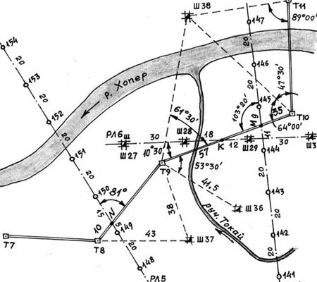
Figure 14.3.3 shows a fragment of the breakdown plan of the production building. The building is designed two-story (two dots in the lower left corner of the building). According to the general plan, this building has the third serial number (number three in the lower right corner).

The mark +110, 50, applied on the building plan, is conditionally accepted on all drawings of the buildings of this master plan as 0.000. The coordinates of the gate axis and the longitudinal axis of the road are also indicated. On fig. 14.3.4 shows a fragment of the layout plan of a residential and civil facility with dimensional reference.