Load turn-on delay circuit. Multiple timing and load off delay relay circuits Load on delay
It is possible to activate and deactivate household appliances without the presence and participation of the user. Most of the models produced today are equipped with a timer for automatic start / stop.
What to do if you want to manage outdated equipment in the same way? Stock up on patience, our advice and make a time relay with your own hands - believe me, this homemade product will be used in the household.
We are ready to help you realize an interesting idea and try your hand at the path of an independent electrical engineer. For you, we have found and systematized all the valuable information about the options and methods for manufacturing relays. The use of the information provided guarantees easy assembly and excellent performance of the instrument.
In the article proposed for study, home-made versions of the device tested in practice are analyzed in detail. The information is based on the experience of enthusiastic electrical craftsmen and the requirements of regulations.
Man has always sought to make his life easier by introducing various devices into everyday life. With the advent of technology based on an electric motor, the question arose of equipping it with a timer that would automatically control this equipment.
Turned on for a specified time - and you can go do other things. The unit will turn itself off after the set period. For such automation, a relay with an auto-timer function was required.
A classic example of the device in question is in a relay in an old Soviet-style washing machine. On its body there was a pen with several divisions. I set the desired mode, and the drum spins for 5-10 minutes, until the clock inside reaches zero.
The electromagnetic time switch is small in size, consumes little electricity, has no broken moving parts and is durable
Today they are installed in various equipment:
- microwave ovens, ovens and other household appliances;
- exhaust fans;
- automatic watering systems;
- lighting control automation.
In most cases, the device is made on the basis of a microcontroller, which simultaneously controls all other modes of operation of automated equipment. It's cheaper for the manufacturer. No need to spend money on several separate devices responsible for one thing.
According to the type of element at the output, the time relay is classified into three types:
- relay - the load is connected through a "dry contact";
- triac;
- thyristor.
The first option is the most reliable and resistant to surges in the network. A device with a switching thyristor at the output should be taken only if the connected load is insensitive to the shape of the supply voltage.
To make a time relay yourself, you can also use a microcontroller. However, homemade products are mainly made for simple things and working conditions. An expensive programmable controller in such a situation is a waste of money.
There are much simpler and cheaper circuits based on transistors and capacitors. Moreover, there are several options, there are plenty to choose from for your specific needs.
Schemes of various homemade products
All the proposed do-it-yourself manufacturing options for time relays are built on the principle of starting a set shutter speed. First, a timer is started with a specified time interval and a countdown.
The external device connected to it starts working - the electric motor or the light turns on. And then, upon reaching zero, the relay gives a signal to turn off this load or block the current.
Option # 1: the easiest on transistors
Transistor-based circuits are the easiest to implement. The simplest of them includes only eight elements. To connect them, you don’t even need a board, everything can be soldered without it. A similar relay is often made to connect lighting through it. I pressed the button - and the light is on for a couple of minutes, and then turns itself off.

To power this circuit, 9 or 12 volt batteries are required, and such a relay can also be powered from 220 V variables using a 12 V DC converter (+)
To assemble this homemade time relay, you will need:
- a pair of resistors (100 Ohm and 2.2 mOhm);
- bipolar transistor KT937A (or analogue);
- load switching relay;
- 820 ohm variable resistor (for adjusting the time interval);
- capacitor at 3300 uF and 25 V;
- rectifier diode KD105B;
- switch to start the countdown.
The time delay in this relay-timer occurs due to the charging of the capacitor to the power level of the transistor key. While C1 is charging to 9-12 V, the key in VT1 remains open. External load is powered (light on).
After some time, which depends on the value set on R1, the transistor VT1 closes. Relay K1 eventually de-energizes and the load is de-energized.
The charge time of the capacitor C1 is determined by the product of its capacitance and the total resistance of the charging circuit (R1 and R2). Moreover, the first of these resistances is fixed, and the second is adjustable to set a specific interval.
The timing parameters for the assembled relay are selected empirically by setting different values on R1. To later make it easier to set the desired time, markings with minute-by-minute positioning should be made on the case.
It is problematic to specify the formula for calculating the issued delays for such a scheme. Much depends on the parameters of a particular transistor and other elements.
Bringing the relay to its original position is performed by reverse switching S1. The capacitor closes on R2 and discharges. After switching on S1 again, the cycle starts anew.
In a circuit with two transistors, the first one is involved in the regulation and control of the time pause. And the second is an electronic key for turning on and off the power of an external load.
The most difficult thing in this modification is to accurately select the resistance R3. It should be such that the relay closes only when a signal is applied from B2. In this case, the reverse switching on of the load must occur only when B1 is triggered. It will have to be selected experimentally.
This type of transistor has a very low gate current. If the resistance winding in the control relay-key is selected large (tens of ohms and MΩ), then the shutdown interval can be increased to several hours. Moreover, most of the time, the relay-timer practically does not consume energy.
The active mode in it begins in the last third of this interval. If the RV is connected through a conventional battery, then it will last a very long time.
Option #2: Chip-based
Transistor circuits have two main disadvantages. For them, it is difficult to calculate the delay time and before the next start it is required to discharge the capacitor. The use of microcircuits eliminates these shortcomings, but complicates the device.
However, if you have even minimal skills and knowledge in electrical engineering, making such a time relay with your own hands is also not difficult.
The opening threshold of the TL431 is more stable due to the presence of a reference voltage source inside. Plus, it requires a much higher voltage to switch it. At the maximum, by increasing the value of R2, it can be raised to 30 V.
The capacitor will take a long time to charge to such values. In addition, connecting C1 to the resistance for discharging in this case occurs automatically. Additionally, you do not need to click on SB1 here.
Another option is to use the "integral timer" NE555. In this case, the delay is also determined by the parameters of the two resistors (R2 and R4) and the capacitor (C1).
“Turning off” the relay occurs due to the switching again of the transistor. Only its closure here is performed by a signal from the output of the microcircuit, when it counts the necessary seconds.
There are much fewer false positives when using microcircuits than when using transistors. The currents in this case are more tightly controlled, the transistor opens and closes exactly when required.
Another classic microcircuit version of the time relay is based on the KR512PS10. In this case, when the power is turned on, the R1C1 circuit supplies a reset pulse to the input of the microcircuit, after which the internal generator starts in it. The shutdown frequency (division ratio) of the latter is set by the control circuit R2C2.
The number of pulses to be counted is determined by switching the five outputs M01-M05 in various combinations. The delay time can be set from 3 seconds to 30 hours.
After counting the specified number of pulses, the output of the Q1 chip is set to a high level, which opens VT1. As a result, relay K1 is activated and turns the load on or off.

The assembly scheme of the time relay using the KR512PS10 microcircuit is not complicated, resetting to the initial state in such a PB occurs automatically when the specified parameters are reached by connecting the legs 10 (END) and 3 (ST) (+)
There are even more complex time relay circuits based on microcontrollers. However, they are not suitable for self-assembly. There are difficulties with both soldering and programming. Variations with transistors and the simplest microcircuits for domestic use are enough in the vast majority of cases.
Option #3: powered by 220V output
All of the above circuits are designed for a 12-volt output voltage. To connect a powerful load to a time relay assembled on their basis, it is necessary at the output. To control electric motors or other complex electrical equipment with increased power, you will have to do this.
However, to adjust household lighting, you can assemble a relay based on a diode bridge and a thyristor. At the same time, it is not recommended to connect anything else through such a timer. The thyristor passes through itself only the positive part of the sine wave of 220 Volt variables.
For an incandescent bulb, fan or heating element, this is not scary, and other electrical equipment of this kind may not withstand and burn out.

The time relay circuit with a thyristor at the output and a diode bridge at the input is designed to operate in 220 V networks, but has a number of restrictions on the type of connected load (+)
To assemble such a timer for a light bulb, you need:
- constant resistance at 4.3 MΩ (R1) and 200 Ω (R2) plus adjustable at 1.5 kΩ (R3);
- four diodes with a maximum current above 1 A and a reverse voltage of 400 V;
- 0.47 uF capacitor;
- thyristor VT151 or similar;
- switch.
This relay-timer functions according to the general scheme for such devices, with the gradual charging of the capacitor. When the contacts are closed on S1, C1 starts charging.
During this process thyristor VS1 remains open. As a result, a mains voltage of 220 V is supplied to the load L1. After charging C1, the thyristor closes and cuts off the current, turning off the lamp.
The delay is adjusted by setting the value on R3 and selecting the capacitance of the capacitor. At the same time, it must be remembered that any touch to the bare legs of all used elements threatens with electric shock. They are all powered by 220V.
If you don’t want to experiment and assemble the time relay yourself, you can pick up ready-made options for switches and sockets with a timer.
More information about such devices is written in the articles:
Conclusions and useful video on the topic
Understanding the internals of a time relay from scratch is often difficult. Some lack knowledge, while others lack experience. To make it easier for you to choose the right circuit, we have made a selection of videos that describe in detail all the nuances of the operation and assembly of the electronic device in question.
If you need a simple device, then it is better to take a transistor circuit. But to accurately control the delay time, you will have to solder one of the options on a particular microcircuit.
If you have experience in assembling such a device, please share the information with our readers. Leave comments, attach photos of your homemade products and participate in discussions. The contact block is located below.
Time relays are used to ensure accurate time intervals when performing various actions using electrical equipment.
They are used everywhere in everyday life: an electronic alarm clock, changing the operating modes of a washing machine, a microwave oven, exhaust fans in the toilet and bathroom, automatic watering of plants, etc.
Benefits of Timers
Of all the varieties, electronic devices are the most common. Their advantages:
- small size;
- exceptionally low energy consumption;
- no moving parts except for the electromagnetic relay mechanism;
- wide range of time exposures;
- independence of the service life from the number of working cycles.
Time relay on transistors
Possessing the elementary skills of an electrician, you can make an electronic time relay with your own hands. It is mounted in a plastic case, where the power supply, relay, board and control elements are placed.
The simplest timer
The time relay (diagram below) connects the load to the power supply for a period of 1-60 seconds. The transistor key controls the electronic relay K1, which connects the consumer to the network with contact K1.1.

In the initial state, the switch S1 closes the capacitor C1 to the resistance R2, which keeps it discharged. The electromagnetic switch K1 does not work in this case, since the transistor is locked. When the capacitor is connected to the mains (upper position of contact S1), it starts charging. A current flows through the base, which opens the transistor and turns on K1, closing the load circuit. The supply voltage for the time relay is 12 volts.
As the capacitor charges, the base current gradually decreases. Accordingly, the value of the collector current drops until K1, by its shutdown, opens the load circuit with contact K1.1.
To reconnect the load to the network for a given period of operation, the circuit must be restarted again. To do this, the switch is set to the lower "off" position, which leads to the discharge of the capacitor. The device is then switched on again by S1 within a predetermined time period. The delay is adjusted by setting the resistor R1, and can also be changed if the capacitor is replaced with another one.
The principle of operation of a relay using a capacitor is based on its charging for a time that depends on the product of the capacitance and the resistance of the electrical circuit.
Two transistor timer circuit
It is not difficult to assemble a time relay with your own hands on two transistors. It starts working if you apply power to the capacitor C1, after which it will start charging. In this case, the base current opens the transistor VT1. Following it, VT2 opens, and the electromagnet closes the contact, supplying power to the LED. By its glow it will be seen that the time relay has worked. The circuit provides load switching R4.
As the capacitor charges, the emitter current gradually decreases until the transistor turns off. As a result, the relay will turn off and the LED will stop working.

The device is restarted by pressing the SB1 button and then releasing it. In this case, the capacitor will be discharged and the process will repeat.
Operation starts when the 12 V time relay is energized. For this, independent sources can be used. When powered from the mains, a power supply is connected to the timer, consisting of a transformer, rectifier and stabilizer.
Time relay 220v
Most electronic circuits operate at low voltage with galvanic isolation from the mains, but can still switch significant loads.
The time delay can be made from a 220V time relay. Everyone knows electromechanical devices with a delay in turning off old washing machines. It was enough to turn the timer knob, and the device turned on the engine for a given time.
Electromechanical timers have been replaced by electronic devices, which are also used for temporary lighting in the toilet, on the landing, in a photographic enlarger, etc. In this case, proximity switches on thyristors are often used, where the circuit operates from a 220 V network.

Power is supplied through a diode bridge with a permissible current of 1 A or more. When the contact of the switch S1 closes, in the process of charging the capacitor C1, the thyristor VS1 opens and the lamp L1 lights up. It serves as a burden. After fully charged, the thyristor will close. This will be seen by turning off the lamp.
The burning time of the lamp is a few seconds. It can be changed by installing capacitor C1 with a different rating or by connecting a 1 kΩ variable resistor to diode D5.
Time relay on microcircuits
Transistor timer circuits have many disadvantages: difficulty in determining the delay time, the need to discharge the capacitor before the next start, short response intervals. The NE555 chip, called the "integrated timer", has long gained popularity. It is used in industry, but you can see many schemes for making a time relay with your own hands.

The time delay is set by the resistances R2, R4 and capacitor C1. The load connection contact K1.1 closes when the button SB1 is pressed, and then it opens on its own after a delay, the duration of which is determined from the formula: t and = 1.1R2∙R4∙C1.
Pressing the button again repeats the process.
Many household appliances use microcircuits with time relays. Instructions for use are a necessary attribute of proper operation. It is also compiled for DIY timers. Their reliability and durability depend on this.
The circuit operates from a simple 12 V power supply from a transformer, a diode bridge and a capacitor. The current consumption is 50 mA, and the relay switches the load up to 10 A. The adjustable delay can be made from 3 to 150 s.
Conclusion
For domestic purposes, you can easily assemble a time relay with your own hands. Electronic circuits work well on transistors and microcircuits. You can install a non-contact timer on thyristors. It can be turned on without galvanic isolation from the existing network.
With the help of electronic relays, you can save money well, for example, take the light in the corridor, pantry or entrance. By pressing the button, we turn on the light and after a certain time it automatically turns off. This time should be enough to search for an object in the hallway, closet or getting into the apartment. In addition, the lighting unnecessarily does not burn if you forgot to turn it off. This device is not only useful, but also very convenient. In this article, we will tell you how to make a time relay with your own hands, providing all the necessary diagrams and instructions.
The simplest option
An example of a constructor for homemade assembly of a shutdown delay timer:
If desired, it is possible to independently assemble the time relay according to the following scheme:
The timing element is C1, in the standard kit of the kit it has the following characteristics: 1000 uF / 16 V, the delay time in this case is approximately 10 minutes. Time adjustment is carried out by variable R1. Power board 12 volts. The load is controlled through the relay contacts. You can not make a board, but assemble it on a breadboard or by surface mounting.

In order to make a time relay, we need the following parts:
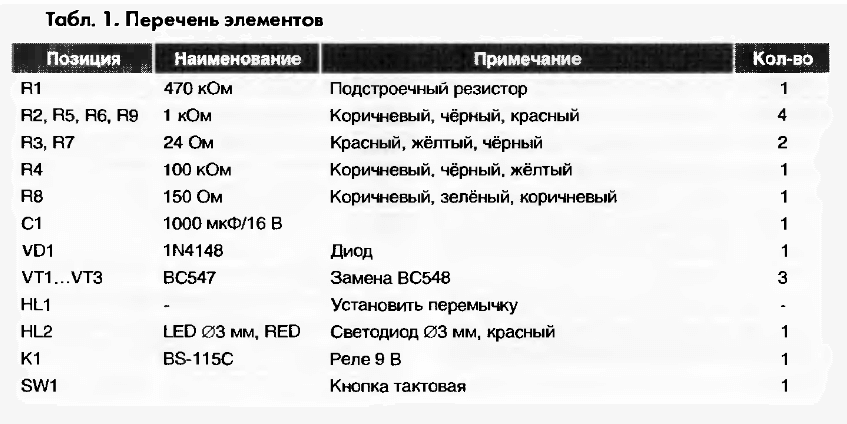
A properly assembled device does not need to be configured and is ready to go. This self-made time delay relay was described in the journal "Radiodelo" 2005.07.
Homemade based on the NE 555 timer
Another do-it-yourself electronic timer circuit is also easy and affordable to repeat. The heart of this circuit is the NE 555 integrated timer chip. This device is designed to both turn off and turn on devices, below is a diagram of the device:

NE555 is a specialized microcircuit used in building all kinds of electronic devices, timers, signal generators, etc. It is quite common, so it can be found in any radio shop. This microcircuit controls the load through an electromechanical relay, which can be used both to turn on and off the payload.
The timer is controlled by two buttons: "start" and "stop". To start the countdown, you must press the "start" button. Disabling and returning the device to its original state is carried out by the "stop" button. The node that sets the time interval is a chain of a variable resistor R1 and an electrolytic capacitor C1. The value of the turn-on delay depends on their rating.
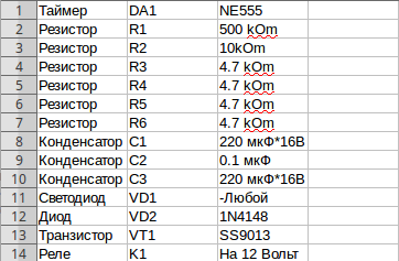
Given the values of the elements R1 and C1, the time range can be from 2 seconds to 3 minutes. An LED connected in parallel with the relay coil is used as an indicator of the state of the design's operability. As in the previous circuit, its operation requires an additional external 12 volt power supply.
In order for the relay to turn on itself immediately when the power is applied to the board, it is necessary to slightly change the circuit: connect pin 4 of the microcircuit to the positive wire, turn off pin 7, and connect pins 2 and 6 together. You can learn more clearly about this scheme from the video, which describes in detail the process of assembling and working with the device:
Relay on one transistor
The easiest option is to use a time relay circuit with just one transistor, KT 973 A, its imported counterpart BD 876. This solution is also based on charging the capacitor to the supply voltage, through a potentiometer (variable resistor). The highlight of the circuit is the forced switching and discharge of the capacitance through the resistor R2 and the return of the initial initial position with the toggle switch S1.
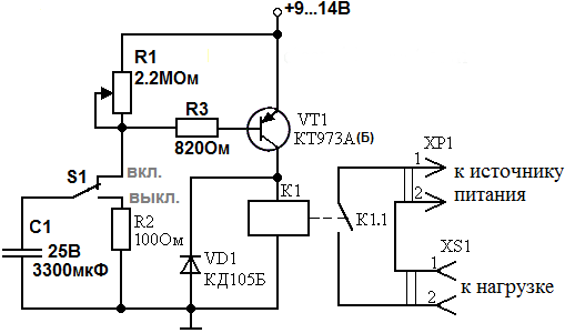
When power is applied to the device, the capacitance C1 begins to charge through the resistor R1 and through R3, thereby opening the transistor VT1. When the capacitance is charged to the VT1 shutdown state, the relay is de-energized, thereby turning off or turning on the load, depending on the purpose of the circuit and the type of relay used.
The elements you have chosen may have a slight variation in denominations, this will not affect the operation of the circuit. The delay may vary slightly and depend on the ambient temperature, as well as on the magnitude of the mains voltage. The photo below shows an example of a finished homemade product:

Now you know how to make a time relay with your own hands. We hope the instructions provided were useful to you and you were able to assemble this homemade product at home!
The 555 series chip was developed a long time ago, but still retains its relevance. On the basis of a chip, several dozens of various devices can be assembled with a minimum number of additional components in the circuit. The simplicity of calculating the values of the components of the body kit of the microcircuit is also its important advantage.
This article will focus on two options for using a microcircuit in a time relay circuit with:
- Turn-on delay;
- Shutdown delay.
In both cases, the 555th chip will function as a timer.
How the 555 chip works
Before moving on to the example of a relay device, consider the structure of the microcircuit. All further descriptions will be made for the microcircuit of the series NE555 manufactured by Texas Instruments.
As can be seen from the figure, the basis is RS flip-flop with inverted output, controlled by outputs from comparators. The positive input of the upper comparator is called THRESHOLD, the negative input of the lower - TRIGGER. The other inputs of the comparators are connected to a supply voltage divider of three 5 kΩ resistors.
As you most likely know, the RS flip-flop can be in a stable state (has a memory effect, 1 bit in size) either in logical "0" or in logical "1". How it functions:
- R (RESET) sets the output to logical "1"(exactly “1”, not “0”, since the trigger is inverse - this is indicated by a circle at the output of the trigger);
- Arrival of a positive impulse to the input S (SET) sets the output to logical "0".
Resistors of 5 kOhm in the amount of 3 pieces divide the supply voltage by 3, which leads to the fact that the reference voltage of the upper comparator (the “-” input of the comparator, it is also the CONTROL VOLTAGE input of the microcircuit) is 2/3 Vcc. The reference voltage of the bottom is 1/3 Vcc.
With this in mind, it is possible to compile state tables of the microcircuit with respect to the inputs TRIGGER, THRESHOLD and exit OUT. Note that the OUT output is the inverted signal from the RS flip-flop.
Using this functionality of the microcircuit, you can easily make various signal generators with a generation frequency independent of the supply voltage.
In our case, the following trick is used to create a time relay: the TRIGGER and THRESHOLD inputs are combined together and a signal is supplied to them from the RC chain. The state table in this case would look like this:
The NE555 wiring diagram for this case is as follows:

After power is applied, the capacitor begins to charge, which leads to a gradual increase in the voltage across the capacitor from 0V and beyond. In turn, the voltage at the TRIGGER and THRESHOLD inputs will, on the contrary, decrease, starting from Vcc +. As can be seen from the state table, the OUT output is logic "0" after Vcc+ is powered on, and the OUT output switches to logic "1" when the voltage drops below 1/3 Vcc at the indicated TRIGGER and THRESHOLD inputs.
Important is the fact that relay delay time, that is, the time interval between power on and charging of the capacitor until the OUT output switches to logic "1", can be calculated using a very simple formula:
T=1.1*R*C
And as you can see, this time does not depend on the supply voltage. Therefore, when designing a time relay circuit, you can not care about the stability of the power supply, which greatly simplifies the circuitry.

It is also worth mentioning that in addition to the 555 series, series 556 in a package with 14 pins. The 556 series contains two 555 timers.
Device with switch-on delay function
Let's go directly to the time relay. In this article, we will analyze, on the one hand, the circuit as simple as possible, but on the other hand, it does not have galvanic isolation.
Attention! The assembly and adjustment of the considered circuit without galvanic isolation should be carried out only by specialists with the appropriate education and approvals. The device is a source of danger, as it contains life-threatening voltage.
Such a device in its design has 15 elements and is divided into two parts:
- Supply voltage generation unit or power supply unit;
- Node with temporary controller.
The power supply operates on a transformerless principle. Its design includes components R1, C1, VD1, VD2, C3 and VD3. The 12 V supply voltage itself is formed on the VD3 zener diode and smoothed out by the capacitor C3.
The second part of the circuit includes an integrated timer with a body kit. We described the role of the capacitor C4 and the resistor R2 above, and now, using the formula indicated earlier, we can calculate the value of the relay delay time:
T = 1.1 * R2 * C4 = 1.1 * 680000 * 0.0001 = 75 seconds ≈ 1.5 minutes By changing the ratings of R2-C4, you can independently determine the delay time you need and redo the circuit for any time interval with your own hands.
The principle of operation of the scheme is as follows. After the device is connected to the network and the supply voltage appears on the VD3 zener diode, and, consequently, on the NE555 chip, the capacitor starts charging until the voltage at inputs 2 and 6 of the NE555 chip drops below 1/3 of the supply voltage, that is, up to about 4 V. After this event occurs, a control voltage will appear at the OUT output, which will start (switch on) relay K1. The relay, in turn, will close the load HL1.
The diode VD4 accelerates the discharge of the capacitor C4 after the power is turned off so that after a quick reconnection to the network of the device, the response time is not reduced. Diode VD5 dampens the inductive surge from K1, which protects the circuit. C2 serves to filter noise on the power supply of the NE555.
If the parts are correctly selected and the elements are assembled without errors, then the device does not need to be adjusted.
When testing the circuit, in order not to wait one and a half minutes, it is necessary to reduce the resistance R1 to a value of 68-100 kOhm.
You probably noticed that there is no transistor in the circuit that would turn on relay K1. This was done not out of economy, but because of the sufficient reliability of output 3 (OUT) of the DD1 chip. The NE555 chip can withstand a maximum load of up to ±225 mA at the OUT output.
This scheme is ideal to control the operating time of ventilation devices installed in bathrooms and other utility rooms. Due to its presence Fans only turn on when you are in the room for a long time. This mode is much reduces the consumption of electrical energy and extends the life of the fans due to less wear of rubbing parts.
How to make a relay with a delay off
The above circuit, thanks to the features of the NE555, can be easily converted into a turn-off delay timer. To do this, you need to swap C4 and R2-VD4. In this case, K1 will close the load HL1 immediately after turning on the device. Load disconnection will occur after the voltage across the capacitor C4 increases to 2/3 of the supply voltage, that is, to approximately 8 V.
The disadvantage of this modification is the fact that after the load is disconnected, the circuit will remain under the influence of a dangerous voltage. You can eliminate this drawback by including the relay contact in the power supply circuit for the timer in parallel with the power button ( It's a button, not a switch!).
The scheme of such a device, taking into account all the improvements, is given below:
Attention! In order for the dangerous voltage to actually be removed from the circuit by the relay contact, it is necessary that the PHASE be connected exactly as shown in the diagram.
Please note that the 555 timer is applied and described on our website in another article that discusses. The circuit shown there is more reliable, contains galvanic isolation and allows you to change the time delay interval using a regulator.
If during the manufacture of the product you need a drawing of a printed circuit board, write about it in the comments.
Related videos