Connection of light from two places. How to connect a pass switch (light control from two or more points)
Basically, one electric switch is used for one lighting device.
So, if you want to turn off the chandelier that is in the living room, you should go into this room. As a rule, only one switching device is installed at the entrance of the room, thanks to which the electric lighting devices in this room are controlled. But sometimes situations arise when this method of controlling lamps is inconvenient. In this article we will look at how to make two switches for one light bulb.
general information
Consider situations where the classic option for connecting fixtures is not justified:
- In the long corridors of the building, which have two exits. If you turn on the light at the entrance to the room, go through the entire corridor and exit, the light will remain on, the light will burn in vain, while a large amount of electricity is consumed per day.
- In houses on landings, where lighting is turned on only on the lower floor for the entire entrance or separately for each floor on the corresponding landing.
- In passage rooms. Even in small apartments, situations arise when a person needs to go into one room and turn on the lighting there. Entering the next room, the resident of the apartment turns on the lamp and returns to the first room to turn off the electric lights, which are no longer needed. In this case, it is more expedient to hold a backup key, thanks to which you can control the switch in the back room.
- For external lights at the entrance to the house. It often happens when you need to use a switch located directly at the entrance to the building to light the porch. If you need to turn on the flashlight at night, you will have to go to the switch in the dark. When you enter the house, turn on the light, then you have to leave the light on for the whole night or immediately turn it off and go up to the apartment in complete darkness.
- At the head of the bed, when you want to turn off the overhead light. Sometimes there is a situation when small lighting is turned on in the bedroom, for example, a sconce or a night lamp, and you have to get out of bed in order to turn off the top chandelier. It is very uncomfortable. To solve this problem, you can use an additional switch on the chandelier, which is installed near the bed.
There are quite a few cases when you have to use duplicate toggle switches. In such situations, a device is used that allows you to turn on and off lighting fixtures from different rooms and different switches, and independently of each other.
Important! This method is very efficient and convenient, besides, it helps to save energy. Using a walk-through electrical switch, for example, you do not have to leave the light on the porch of the house for the whole night. On the top floor, you can turn it on and turn it off near the front door.
How to put two switches on one bulb? Peculiarities
It is not difficult to connect two or more switches to one lamp or lamp. Such a scheme has one significant drawback in terms of the convenience of controlling a lamp or luminaire. So, for example, if you use switch “A” to turn on the light, you will not be able to turn it off with switch “B”, and you will only have to use the same “A”. This situation causes inconvenience and confusion.
Important! If it is important for you that the luminaire is controlled by two switches that are connected to each other, using one switch to turn on the light, you could use the other to turn it off, and vice versa, you should use switches, or so-called pass-through switches. In addition, you need to change the connection scheme.
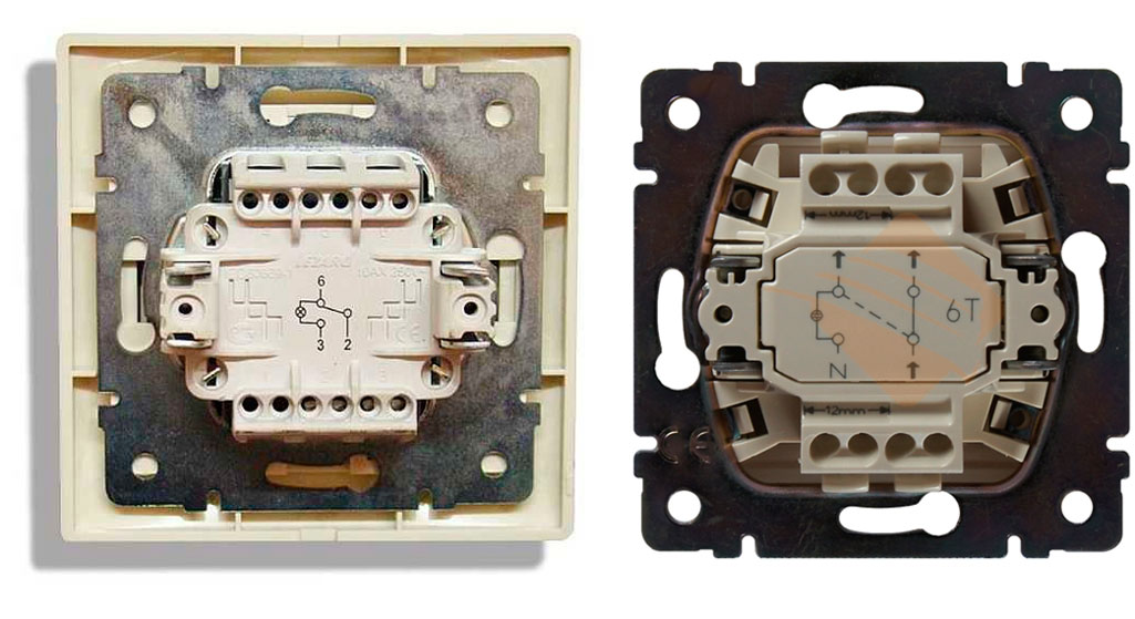
The main difference between the feed-through switch and the standard version of the switching device is the design feature:
- Such a switch has three rather than two contacts and has the ability to switch phases in turn from one contact to the other.
- If a standard switch is characterized by simply breaking or connecting an electrical circuit, then if a switch is installed, when the electrical circuit is broken on one conductor, it switches to another conductor, which served as the name for the corresponding element.
Important! Lighting devices that are connected according to this principle can be both incandescent lamps and fluorescent lamps. In addition to lighting fixtures, other devices that need an on and off circuit can be connected in a similar way.
Schematic features
Installing such a circuit is not difficult, but care is required to connect it.
Important! At the stage of creating wiring at the points where the installation of throw-over structures is planned, it is necessary to lay a three-core cable in advance before the first two. If you need more switches, then you will have to use a four-wire cable that you need to stretch to the next.
In order to be able to control the lighting simultaneously from two places, it is required to purchase walk-through switches that are equipped with two switching positions and three contacts. In this case, the switching must have a toggle character, while the first node must be common to the other two.
Important! One switching position is characterized by the closure of the first, and in the second, the subsequent contact is closed. Therefore, initially there is no closure of three connections at the same time.
Accessories
When considering power line circuits that have two changeover switching structures, the following components can be distinguished:
- a junction box, the so-called branch box, which is used to protect connecting electrical cables - is present in every room, several of them are installed in large rooms;
- connecting wires, which are two, three and four-core;
- directly the lamp itself;
- pass-through switching devices in the amount of two pieces.

Connection principle
Consider how the connection diagram of a lamp with two switches looks approximately:
- The zero wire is laid from the source to the junction box, then the wire goes to the lamp.
- The phase wire is drawn from exactly the same source to the same box, and then laid to the common contact of the first switch.
- Two changeover contacts of the first switch, using a junction box, are connected to exactly the same parts of the second switch.
- The phase from the common contact of the second switch is connected to another electrical node of the lamp.
Installation work of the control system of one lighting device, functioning from two places at the same time, is not complicated. Consider how the installation is carried out:
- In the required places, we install changeover switching structures.
- From them we derive three-core cables.
- We mount one or, if necessary, several electric lamps. which are connected in parallel to each other.
- We derive a two-core cable from one or several lighting fixtures.
- We install the junction box, while choosing a place, the location point of which corresponds to convenient access to the box itself and the shortest distance of the cable length.
- To the box we bring wires from flip structures, power and the lighting fixtures themselves.
- We connect them, as described in the above paragraphs.
Important! Such a system involves connecting four contacts (two pairs) to each other. When the lighting is turned on, the phase from the common node of the second electric switch approaches the lighting fixture.
Security conditions
How to make 2 switches for one bulb? Mounting work of walk-through switches is possible both with open and hidden wiring systems. Installation can be carried out independently, only the necessary safety rules must be observed:
- Before proceeding with the installation work, it is required to de-energize the apartment.
- It is necessary to correctly determine the location of the phase and zero.
- The wires should be connected with a neat twist, while crimping and isolating them.
- On the surfaces it is recommended to rigidly fix the electrical fittings and the junction box.
- Based on the power of the electricity consumed, it is necessary to determine the power parameter of the lighting device and select a three-core cable of the required section.
Important! Due to the design feature, there is no specific “on” or “off” position on the key of the backup electric switches. Based on the position of the electrical contacts of another switch, the two connecting nodes of this system correspond to the position “closed” or “open”. Therefore, when the light is off, the key will be in a different position each time. This feature is not a problem and you can quickly get used to it.
In most cases, standard one-two- or three-gang switches are initially mounted in each house or apartment, which control lighting from only one specific place. But this is extremely inconvenient, because how many times have you had to get out of bed to turn on the lights in the room?
With modern wiring, pass-through switches have become more often used, which are able to turn off or turn on, for example, the lighting in the room when entering the room and at the same time near the bed or, for example, on both sides of the corridor. How to do it? Very simple! To do this, it will be enough just to read this article.
What is a pass switch

It is a multi-contact switch that is capable of simultaneously controlling a light source from multiple locations. In the modern market of electrical installation materials, this device is represented by the following types:
- single-keyboard with one input and 2 outputs;
- two-key with two inputs and 4 outputs;
- three-key with three inputs and 6 outputs;
- cross with two inputs and two outputs for lighting control from more than 3 places.

This type of device can be both keyboard and touch or remote (control from the remote control). In most cases, standard key switches are used, however, in the case of installing the Smart Home system, it is better to mount remote walk-through switches that are controlled using a remote control or a special smartphone application.
The principle of operation of the pass switch
In appearance, the through switches are identical to the standard ones, however, due to the design, their principle of operation is significantly different.
So when you press the key of a conventional switch, the circuit simply closes or opens, and if you press the key of the pass-through switch, it opens one group of contacts and closes another.
Important! Unlike standard two-key (single-key) devices, pass-through switches can only work in pairs, since one and the second control the phase supply to the lighting device and if one of them is not in the circuit, then the phase wire will not come to the light source, as a result of which the light bulb will not light up.
Scheme of connecting electric switches through passage for lighting control from 2 places

Allows you to effectively control the lighting from 2 points when turning the lighting on and off:
- on the flight of stairs in the cottage;
- in a long corridor;
- in office premises;
- in passage rooms;
- in the bedroom (control of lighting circuits near the bed and at the entrance to the bedroom) and so on.
To answer the question: “how to connect a 2-key pass-through switch?” you need to understand the principle of its operation. Let's do this and do it on the example of the photo presented above.
In this scheme, the neutral conductor (in most cases blue) from the junction box is connected directly to the light source (bulb). The phase wire (brown) from the junction box comes to the 1st contact of the feed-through switch No. 1, after which it goes from the first contact of switch No. 2 to the second end of the light bulb.
At the same time, jumpers must be installed between contacts No. 2 and No. 2, as well as contacts No. 3 and No. 3 of through switches No. 1 and No. 2 (these jumpers are connected in the junction box).
Thanks to these jumpers, the phase to the light source can be supplied either from one or the second switch, which will allow you to turn on the lighting from several places.
This is considered the simplest circuit as it only allows one light source to be controlled. In order, for example, to turn on the LED backlight and the main lighting separately, you need to use a two-button one, the principle of which you will find in the next section.
Control circuit for a two-gang pass-through switch

The principle of operation and the connection diagram of a two-gang pass-through switch are similar to those of a single-gang switch, however, unlike the previous ones, these devices allow you to control lighting in several groups.
Consider the principle of operation of these devices according to the following photo:

In this scheme, mounted:
- two double switches;
- power supply 220 V (phase and zero);
- junction box in which switching is performed;
- 2 groups of lighting circuits (for example, this can be a chandelier and LED lighting in a hall or room).
In this scheme, "0" (with the correct switching of blue color) is connected directly from the junction box to one output of the 1st and 2nd lighting groups. Next, the phase wire (brown) enters the junction box and leaves it and connects to outputs No. 1 and No. 2 of the through switch No. 1.
Further, the outputs from the passage switch No. 1 with numbers No. 3, 4, 5, 6 go to the junction box, in which they are switched with similar outputs No. 3, 4, 5, 6. Further from the outputs No. 1 and No. 2 of the passage switch No. 2 the phase goes to the 1st and 2nd lighting groups and is connected to the second contact.
How to install in a junction box

In order for double or lighting devices to perform their function for many years, the switching process must be approached thoroughly.
Often, due to negligence or lack of extensive experience in electrical work, twists can be found in junction boxes. However, this is a gross violation, because over time, contact may be lost in these twists, as a result of which the wires will begin to heat up, burn out and a fire will occur. It is also strictly forbidden to connect copper and aluminum wires without any layer.
For a reliable connection of cable and wire products in junction boxes, 3 methods are recommended:
- Soldering contacts.
- Welding conductors using special transformers.
- Connection of conductors using special clamps (WAGO).
Basic recommendations for the installation of two-button switches
When installing both standard and two-button switches, it is recommended:
- The placement height from the floor level should be 90 cm.
- The distance from the door or window opening to the pass switch must be at least 15 cm.
- Distribution boxes with switching must be located in a visible place and at the same time they must be placed at a distance of 15-30 cm from the ceiling level.
- It is recommended to use a 3-core flexible cable with a cross section of 1.5 mm² (VVGng, PVSng, ShVVP, and so on) for the installation of walk-through switches.
- Cable and wiring products must be laid in corrugation, in strobes or cable channels.
- All metal surfaces of fixtures must be grounded without fail.
conclusions
Pass-through single-gang and two-gang switches are modern switches that allow you to organize the control of one or more light sources from different places in one or neighboring rooms.
As can be seen from the above information and photo, it can be said that despite the design (single-gang or double-gang switch, the connection diagram for 2 sources) is very easy to install and allows you to effectively control the lighting in a huge cottage, large commercial premises or in industrial buildings.
To connect these devices will be enough:
- two pass switches for 2 keys or two single-key switches;
- junction box;
- flexible cable with three cores.
Related videos
Prices for housing and communal services are increasing every year, which makes us think about saving, including electricity. Moreover, this applies to those places that people did not even think about before. For example, lighting stairs and landings in multi-storey buildings. In the recent past, when electricity prices were miserable, stairs were illuminated 24 hours a day. This problem is also relevant in private houses with more than one floor connected by a staircase. To save money, the light has to be turned off, but for this you need to either go down the stairs again or go up it. This is extremely inconvenient, so sometimes they simply do not turn it off and it burns until the morning, when it becomes light.
For the convenience of lighting in such areas, the so-called "pass-through" switches were developed. They are also called "duplicate" or "flip". They can be distinguished from classic switches by the presence of a larger number of contacts. Therefore, in order to connect them, you need to know the circuit, and even more so, be able to understand the principle of their operation. Naturally, this is not entirely simple, but absolutely real.
On the key of the pass-through switch there are two arrows (not large), directed up and down.
 This type has a one-button switch. There may be double arrows on the key.
 The connection diagram is not much more complicated than the connection diagram of a classic switch. The difference is only in a larger number of contacts: a conventional switch has two contacts, and a pass-through switch has three contacts. Two out of three contacts are considered common. In the lighting switching circuit, two or more similar switches are used.
 Differences - in the number of contacts
 The switch works as follows: when switching with the key, the input is connected to one of the outputs. In other words, the feed-through switch is designed for two operating states:
- Input connected to output 1;
- Input connected to output 2.
It has no intermediate positions, therefore, the circuit works as it should. Since there is a simple connection of contacts, according to many experts, they should have been called "switches". Therefore, the transitional switch can be safely attributed to such devices.
In order not to be mistaken what kind of switch, you should familiarize yourself with the switching circuit, which is present on the switch housing. Basically, the circuit is available on branded products, but you will not see it on inexpensive, primitive models. As a rule, the circuit can be found on switches from Lezard, Legrand, Viko, etc. As for cheap Chinese switches, there is basically no such circuit, so you have to call the ends with the device.
As mentioned above, in the absence of a circuit, it is better to call contacts at different key positions. This is also necessary in order not to confuse the ends, since irresponsible manufacturers often confuse the terminals during the production process, which means that it will not work correctly.
To ring the contacts, you must have either a digital or pointer device. The digital device should be switched to dialing mode with the switch. In this mode, short-circuited sections of electrical wiring or other radio components are determined. When the ends of the probes are closed, the device emits a sound signal, which is very convenient, since there is no need to look at the device display. If there is a pointer device, then when the ends of the probes are closed, the arrow deviates to the right until it stops.
In this case, it is important to find a common wire. For those who have the skills to work with the device, there will be no particular problems, but for those who picked up the device for the first time, the task may not be solvable, despite the fact that only three contacts need to be sorted out. In this case, it is better to first watch the video, which clearly explains, and most importantly shows how to do it.
Wiring diagram for two pass switches
Such a scheme can be of great help in organizing lighting on the stairs (in a two-story house), in a long corridor or in a walk-through room. It can be quite convenient to arrange lighting in the bedroom when one switch is installed at the entrance to the bedroom, and the other next to the bed. In this case, you do not have to constantly get out of bed to turn off the main light.
 Wiring diagram for two walk-through switches
 The connection diagram is very simple and understandable: a phase is applied to the input of one of the switches, the input of the other switch is connected to one of the wires of the chandelier (lamp). The second end of the lamp is connected directly to the neutral wire. The N1 outputs of both switches are connected together, as are the N2 outputs.
The circuit functions quite simply. If you look at the diagram, then in this position the light source is turned on. At the subsequent switching of any of the switches, in random order, the lamp will either turn off or turn on.
In order to make it more clear, you should carefully look at the figure.
 Wiring between two switches.
 In the case of installing such switches indoors, the wiring should be done as shown in the figure below. Modern requirements allow wiring at a distance of 15 cm from the ceiling. As a rule, the wires are placed in special trays or boxes, and the ends of the wires are concentrated in mounting (junction) boxes. This approach has undeniable advantages. The main thing is that a damaged wire can always be replaced. Connection of wires in mounting boxes is carried out using special clamps (contact blocks). At the same time, twists are also allowed, which are then necessarily soldered and reliably isolated.
The output of the second switch is connected to one of the conductors leading to the lighting lamp. The white conductors are the wires connecting the outputs of both switches.
 Wiring in residential area
 How the ends of the wires are connected in the junction box can be found out by watching the corresponding video.
Three-point lighting control option
If there is a need for remote control of the lamp from three places, then you will also have to purchase a cross switch. It switches not one, but two contacts at a time, so it has two inputs and two outputs.
How to connect all three switches can be seen in the figure. This is somewhat more complicated than the previous case, but you can understand the principle of operation.
 Electric circuit for turning on a lamp from three places.
 To connect an electric light source, according to this scheme, you must do the following operations:
- The neutral wire is connected to one of the lamp wires.
- The phase wire is connected to the input contact of one of the feed-through switches.
- The free wire of the lamp is connected to the input contact of the second switch (through).
- The two output contacts of the pass switch are connected to the two input contacts of the cross switch.
- The two output contacts of the second pass switch are connected to the two output contacts of the cross switch.
The diagram is the same, but it is shown more clearly where exactly to connect the wires.
 What terminals are the wires connected to.
 Approximately so it is necessary to spread the wires around the room.

Based on the scheme for three control points, it is possible to assemble schemes for 4 or 5 points. In such cases, it is necessary to increase the number of cross switches. They should always be installed between two feed-through switches.
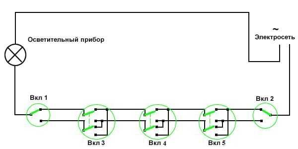 Scheme of organization on / off the lamp for 5 points.
 If one of the cross switches is removed from this circuit, then a 4-point option will be obtained, and if one cross switch is added to it, then a 6-point option will already come out.
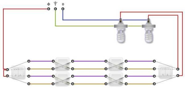
Two-gang pass-through switch: wiring diagram
In order to control the operation of two lamps from several points, there are two-button walk-through switches. They have six contacts. The main thing is to identify common contacts. They are determined according to the same principle as when searching for a common contact in single-gang switches.
In a circuit that uses two two-button walk-through switches, much more wires are used.
The phase wire is fed to the inputs of both switches, and the other inputs of the switches are connected to one of the ends of one and the other lamp. The free ends of the lamp are connected to the neutral conductor. Two outputs of one switch are connected to two outputs of the second switch, and the other two outputs of this switch are connected to the other two outputs of the first switch.
 Wiring option for connecting two-button walk-through switches.
 If you want to control the operation of two lamps from three or four points, you will have to purchase two cross switches. Each pair of two-gang switch outputs is connected to one pair of one cross switch. And so on, pair after pair of device outputs are interconnected.
 Control of the operation of two lighting lamps from four points.
 If you look, then there is nothing complicated, especially when using single-key switches. As for the two-button walk-through switches, everything here is much more serious and costly, both in terms of wires and switches. And to be more precise, this scheme is less practical, but more expensive.
Home electrical is one of those jobs that most of us prefer to leave to the experts. And, nevertheless, to replace a failed electrical outlet or a simple single-circuit lamp, many owners still decide on their own. But such a task as connecting a two-gang switch to two bulbs raises some questions - both the switch itself with an “extra” contact, and again an “extra” wire in the mounting opening. And the abundance of connections in the junction box is simply shocking. We will try to dispel some of the fears and doubts. Moreover, two, or even three-circuit lamps have recently been not an exception, but rather the rule.
A separate conversation is summer cottage construction. What kind of lighting schemes for arbors and adjacent territories are not invented by the owners of the hacienda. How to connect two switches to two light bulbs in such a way that, depending on the need, increase or decrease the level of illumination?
A few words about electric current
Without “loading” with theory and complex physical concepts, let us recall the elementary basics of electrics. The household electrical network has a voltage of 220 V, the type of current is alternating. What does it mean? One of the contacts, the "phase", has a constantly changing potential from "+" to "-" (50 cycles per second), and the other "zero" serves as a kind of battery, allowing electrons to accumulate in excess, then flow back.
Each lamp has two contacts: ground and central. In order for our lighting device to start working, zero and phase must be connected to these two contacts. Moreover, in the case of alternating current and an ordinary household lamp, polarity does not play any role.
But the location of the "zero" and "phase" is still necessary to know. There is a special device - a "probe", with which it is determined which of the wires is phase. This must be borne in mind for the correct inclusion in the circuit of the disconnecting device - the switch. It must necessarily break the “phase”, these are the security requirements.
Connection diagram of a simple lamp
On the example of the simplest single lamp, "Ilyich's light bulb", let's consider the main elements of the electrical circuit.
In any apartment, wiring is usually laid in the wall around the perimeter at a distance of about 10-15 cm from the ceiling. This is a highway. It has junction boxes. They are needed in order to "crash" into the main cable, power an outlet or a switch with a lamp.

Consider the wiring diagram in the junction box. Down from it goes the cable to the switch, up - to the lamp, to the left and right - the main cable. In fact, this, of course, is a convention, the order of inserting wires into the box is determined only on the basis of considerations of expediency.
Zero wire, it's easy with him. It branches off directly from the highway and goes straight to the lamp. The situation with the phase wire is not much more complicated, it also goes to the lighting fixture, but only through the switch. That's all wisdom.

A conventional single-gang switch has two contacts on the back for connecting wires. In this case, polarity does not matter. And how to connect a chandelier to two switches? Will the task become much more difficult?
Double-circuit chandelier - connection diagram
For a more rational use of electricity in apartments, lamps with two or even more circuits are often used. In fact, this is the same as connecting two switches to two light bulbs. The scheme can be as follows: one key of the switch lights two lamps in a chandelier out of five, the remaining lamps turn on the second key. The scheme is not complicated, but, nevertheless, it allows you to use three lighting options in the room at once:
- weak light - the first key - two lamps;
- medium light - second key - three lamps;
- strong light - both keys - all five lamps.

How to properly connect a switch with two keys is shown in the diagram. The neutral wire is routed directly from the junction box to the fixtures. The wiring of "zero" for individual lamps, as a rule, is already done at the lighting manufacturer, and the electrician only connects "zero" to the black or blue terminal.
The “phase” is sent to a double switch, from which two wires come: for the first and second circuits.
Replacing a two-gang switch with two single-gang ones
If necessary, one double switch can be easily replaced by two single ones. The only thing you need for this is a short jumper between the receiving terminals.
How to connect two switches to two light bulbs, the diagram is shown in the figure. It shows how simply, without any special tricks, a two-gang switch is replaced by two single-gang ones.

Such a scheme can be justified not only by the absence of a two-gang switch in the household. Sometimes lighting, say, a parking lot for a car in a country house, is a good idea to make it controllable from different points: from the exit door of the house and from a device mounted on a gate post.
And then we smoothly move on to the next topic. In the same way as connecting two switches to two light bulbs, but much more practical, you can use walk-through switches.
What is a pass switch?
What are these devices and where are they used? In addition to the considered option, how to connect two switches to two light bulbs, there is a better opportunity: using two switches located at different points, control one lighting fixture.
The device of standard household switches, as a rule, is of the same type. There are two contacts - fixed, fixed on the body of the device and movable, mounted on the rocker. The rocker changes its position under the action of the key. The device respectively has two positions "On" and "Off".

The pass switch (it would be more correct to call it a "switch") does not have an "Off" position. As can be seen from the figure, it has the provisions:
- 1 line included;
- line 2 included.
What are toggle switches used for?
One option for using walk-through switches is the same as discussed earlier: a lamp or spotlight that illuminates a private parking lot. The use of pass-through devices will make it possible to turn on the site lighting from one point, say, from the corridor of a garden house, and turn it off from another. For example, just before leaving, a switch mounted on the entrance gate. Moreover, the order of on-off can be absolutely anything.
The second option is a long corridor devoid of natural light. The light turns on at its beginning and turns off at the end or vice versa. Comfortable? Undoubtedly. So before you connect two switches to two light bulbs, you should think carefully about whether to replace this circuit with a variant with pass-through switches.
Corridor lighting scheme using two walk-through switches
Externally, pass-through switches are almost no different from ordinary ones. Only on the reverse side, instead of two, there are three terminals:
- phase;
- L#1;
- L#2;
How to connect the lamp to two switches correctly is shown in the diagram.

"Zero" on the lamp comes through the blue wire. Phase - in red. The figure clearly shows that the lamp will be powered only if both switches are in the same positions. Changing the position of the key on any of the devices will break the circuit and cut off the power to the lighting device. Well, after the light is turned off, clicking any of the switches will close the circuit again, and our corridor will be illuminated again.
In stairwells, in long corridors or tunnels, instead of expensive infrared sensors, you can simply connect two walk-through switches.
Installation Safety Precautions
Here is a set of some standard rules to avoid trouble when installing lighting fixtures:
- The switch cannot be set to "zero", it must always break the "phase". Only in this case is the switch in the "off" position. allows you to carry out any repair work with the lamp, up to its replacement, without de-energizing the whole house.
- When connecting wires in a twisted junction box, in no case should aluminum and copper wires be connected to each other. Metals with different potentials form a galvanic pair, the contact will weaken over time, it will begin to “sparkle”. Sometimes this leads to fires.
- Before starting work, you should stock up on a probe to determine the phase wire and, just in case, thick rubber gloves.
- It is not necessary to seal open wiring (at least in double insulation, even in triple insulation, it doesn’t matter) with paper wallpaper, other combustible finishing materials.
- Do not use used wiring. It is not known what loads it was subjected to in the past, and it is impossible to check the condition of each strand inside the braid throughout its entire length.
In order not to get confused when installing electrical wiring, it is better to buy wires with different colors of cores. The phase, as a rule, is connected to a white or red wire, zero to blue or black, and yellow, green or yellow-green is used for grounding.
When laying wiring under a layer of plaster, it is worth keeping the wire layout. This may be needed in the future. The easiest way is to take a picture of the wiring that has not yet been walled up, putting directly on the wall with chalk or a marker the distance from the walls, ceiling, corners, window openings, and other landmarks.
Calculations of the wire cross section should not be made to a minimum, it is better to give some margin. Then your head will not hurt when buying a new large plasma panel or installing a dishwasher in the kitchen, and in the country, if necessary, you can safely connect a household welding machine or electric saw to the network.
As an electrical engineer, I only discovered the existence of a walk-through switch while building a house. It seemed undignified to me to return to the hallway after turning on the lighting in the living room in order to turn off the lamp at the front door.
In the end, I applied them on four occasions. It's funny, but a few years after the house was finished, it dawned on me that this had to be done three more times!
Now, based on the experience gained, I strongly recommend that you familiarize yourself with the wonderful properties and possibilities of a simple and useful device.
 Pass-through switch: what is it about?
In academic terms, a walk-through switch is a device that provides independent control of lighting from different locations. For clarity, you can play: one person tries to turn on the lamp, and the other - turn it off. At the same time, they control the lighting from different places. It will turn out a fun disco with blinking lamps, but it's impossible to win!
In practice, such devices are used to turn on the light at one point, pass a certain area comfortably and turn off the light at another point without going back. Hence the name - through passage or mid-flight switch. In this case, the whole trick lies in the scheme of the device.
 Let's compare a conventional switch with a pass-through
 As you can see, when a third contact is added to a conventional switch, it becomes a pass-through. Moreover, from the point of view of circuitry, it is correct to call such a device a switch, since the circuit never breaks and the switching contact, in any position of the key, is connected to one of the output contacts.
Application examples
It is far from always obvious where exactly the control of luminaires should be provided. The task is simplified if you look at practical examples.
 Lighting control between garage and home
 In this case, mid-flight switches are used to provide lighting for the path between the garage and the house:
- lighting control in the garage;
- lamp above the door to the garage;
- illuminated path;
Thus, you can turn on the light from the house, walk comfortably through the illuminated area and turn off the lights already in the garage, or vice versa. In this particular example, there are two more possibilities:
- when working in the yard, you can turn on the lighting;
- if you are waiting for guests, you can control the light on the street while at home.
I added a light sensor to the lighting circuit of the local area, and the lights in the yard turn on automatically at nightfall, if necessary. Read about the use of the sensor in a separate article.
 Pass-through switches control the lighting in the vestibule
 It is not very comfortable in the dark vestibule of the house, and marching switches are also installed to control its lighting:
- porch lighting control;
- lamp on the wall;
- hallway lighting control.
Now we close the front door, turn on the lights in the hallway, and turn off the lights on the street and in the vestibule. To control the light on the way from the hallway, you would have to install walk-through switches in all three rooms on the first floor. To avoid this, the lighting in the hallway is turned off by a timer. Read about its installation in a separate article.
 Climb up the illuminated stairs and turn off the light
 To illuminate the stairs, mid-flight switches are a necessity:
- lighting control in the living room on the ground floor;
- three lamps at the stairway;
- lighting control on the second floor area.
The landing on the second floor is small, so after turning on the lights in one of the rooms, you can go back and turn off the lamps on the stairs. This did not suit me, and a timer was added to the switch wiring diagram. Now it can be turned off immediately, and the lighting will turn off the timer after 2 minutes.
 We descend into the basement along the illuminated stairs
 We also go down the illuminated stairs to the basement floor:
- lighting control at the entrance to the basement;
- lighting control in the basement.
In the basement, everything is a little simpler: here, in one block, you can turn on the lamp in any room. Thus, you can first turn on the light in one of the rooms, and then turn off the lighting of the stairs.
 An example of installing walk-through switches in a bedroom
 Here is a blatant example of hindsight: there are no walk-through switches in the bedroom! You have to turn off the lights at the door, and then move in complete darkness by touch, risking bumping into the corner of the bed. You can, of course, turn on the sconce, and then return to the entrance again and turn off the general light. Do it right like this:
- lighting control at the front door;
- sconces at bedside tables;
- as an option, you can use the lamps in front of the bed;
- headboard lighting control.
Approximately the same thing should have been done in 2 other bedrooms. I hope these examples will inspire you to make the right decisions.
Varieties of cross and pass switches
Let's take a closer look at the subject of our interest. First, we will study the existing options, and then we will learn how to connect them to the wiring.
 The main types of walk-through switches
 In appearance, toggle switches differ in color and shape, and they also come in:
- hidden or open installation;
- single-key, two-key, three-key;
- with or without illumination;
- a special character on the keys may or may not be present.
 Internal circuits of walk-through switches
 Considering the internal scheme, we can talk about the following types:
- Single key switch. It is used most often as the first and last device in case of 2 or more control points.
- Pass-through switch with two keys. A double device is used for the same purpose to control lighting using 2 groups of luminaires.
- 3-key pass switch. Used for the same purpose to control three groups of luminaires.
- One-key crossover or toggle switch. It is used as an intermediate device in a chain of three or more locations.
- Double cross switch. It is used as a middle device in a chain of 3, 4 or more control points for two groups of luminaires.
As follows from the above illustration, in the feed-through switch, the input terminal is connected to one of the output terminals when the key is pressed. In cross - the conductors connected to the input and output are reversed when the position of the key is changed.
There is no point in worrying about the variety of internal circuits at the moment. Firstly, only a single pass-through switch is most often in demand. Secondly, something else may be required, and this will become clear from the specific options for connecting devices.
 Rear view of various types of pass-through switches
 The photo shows a rear view of the wiring accessories. Now you can choose and purchase the right model yourself. Unfortunately, not all manufacturers indicate the marking of the contacts on the device case. In its absence, you will have to use a multimeter to find out the placement of the terminals of the product.
Wiring diagrams for walk-through switches
The way of disconnection of mid-flight switches is determined by the specific conditions of use. In several cases, we will consider 2 options for the connection image. The first of these is easier to understand and is sufficient when installing appliances in the case of existing electrical wiring. Another option takes into account the requirement of cable laying using junction boxes, which can be done in a new building or when replacing wiring.
Standard 2-point installation
The option of controlling one or more parallel-connected lamps from two locations is the most popular and simple. There are four possible combinations of the positions of the keys of the two switches: in two of them the lamp is on, in the other two it is off.
 The most popular scheme for connecting two walk-through switches with one lamp
 In the example with a photo of devices at the back, the circuit is open, and the lamp does not light. At the bottom of the illustration, the circuit is closed and the light is on. It can be said that in this connection scheme, one conventional switch is replaced by two single-key feed-through switches connected to each other by a two-wire cable.
 Wiring diagram for connecting two switches with a light bulb
 This illustration shows the connection using a junction box. As you can see, each of the devices is connected to the box with a three-wire cable.
Control schemes for one luminaire from several points
Multi-point control is essential when driving on a long walkway. For example, in a three-story house on each floor, you can control the lighting on the stairs where necessary.
 Option to control one luminaire from three points
 To implement an independent lighting control scheme from three locations, a cross switch is required. As in the previous version, they can be interconnected with a two-wire cable.
 Installation of three pass-through switches using a junction box
 Now let's get acquainted with the wiring diagram, made in accordance with all the rules, using a junction box. As you can see, a three-wire cable is required to connect two pass-through switches to a junction box, and two two-wire cables will have to be used for a crossover one.
 Connection diagram of four pass-through switches for controlling one lamp
 By the same principle, you can build a lighting control scheme from 4 or more locations. The first and last device in the circuit are walk-through switches. Intermediate devices - cross type.
Control multiple lights from multiple locations
There are situations when it is necessary to control several luminaires from several locations. For example, in a bedroom, it is possible to install one two-gang pass-through switch at the door, and the other at the bed. Then in both places it will be possible to turn on and off both the general lighting in the room and the lamps by the bed.
 Connection diagram of two pass-through switches with two separate luminaires
 To implement such a scheme, two two-button walk-through switches are required. To connect them, in the simplest case, two two-wire cables are needed.
 Wiring diagram for connecting two switches with two separate luminaires
 The wiring diagram for the correct connection of a two-gang pass-through switch using a junction box looks more impressive. The box will need a large size, as eight wire connections must fit in it. To connect the first pass-through switch, you will need a two-wire and three-wire cable, and to connect the second one, two three-wire ones.
 Control scheme for three independent lamps from two points
 Theoretically, by increasing the number of walk-through 2-key switches, it is possible to independently control the lighting of 2 lamps from any number of places. You may want to operate from two locations with three groups of light bulbs in a chandelier. A circuit using a triple switch demonstrates the real possibility of such work, however, it will require a lot of cable.
 Control scheme for two lamps from three places
 This wiring diagram of a 3-way switch demonstrates the ability to control two separate bulbs. Two two-key walk-through switches can stand by the bed, the third - at the bedroom door. Everywhere you can turn on and off local lighting, or a general lamp.
 Control scheme for two separate lamps from four points
 As we have already noticed, the lighting control scheme can be increased indefinitely. The ability to turn on and off 2 different lights from four points can come in handy in a long hallway of a house with a lot of rooms. Obviously, after considering various examples, it will not be difficult to draw up any scheme for independent lighting control using single-key and other pass-through switches.
Installation of walk-through switches with existing wiring
It is likely that you will want to equip your own hands with independent control of fixtures with existing electrical wiring. In this case, it is quite difficult to provide electrical installation using a box and laying a cable 15 cm from the ceiling, because it is possible to damage the wiring in the wall.
In any case, you need to get a tester to detect the cable under the plaster and check for its presence where you are going to do something. In addition, when performing work, the wiring in the house or apartment should be completely de-energized.
 Installing pass-through switches with existing wiring
 Consider step by step the option of lighting control from 2 points. It follows from the above illustration that the No. 1 through switch can be installed instead of the existing conventional one. To install device No. 2, you should prepare a place in the wall, which can be read in a separate article.
The next step is to make a strobe connecting both devices. A three-core cable is laid in the seam and the wall is puttied.
From the wiring diagram it can be seen that the green core of the three-core cable coming from device No. 2 should be connected to the corresponding core of the cable coming from the junction box to device No. 1. The connection is placed in the socket of device No. 1 and is made by twisting, or using a special clamp. It is better to solder the twist and wrap it with electrical tape. Nothing needs to be changed in the distribution box.